
A previous post provided information about how specified and unspecified inch dimensioning and tolerances are applied in a general note or in the title block of technical and engineering drawings. The same strategy does not apply to metric dimensioning because metric dimensions don’t have trailing zeros attached to or included beside them.
ISO 2768 standard (or the General Tolerances developed by ISO) regulates metric tolerancing, and the ISO 2768 standard on tolerancing is based on the size of drawing or object features, with small feature sizes having closer tolerances and larger feature sizes having larger tolerances. Four classes of size tolerances are usually applied to drawings, and each class has its abbreviation in parentheses:
- fine ( f)
- medium (m)
- coarse (c), and
- very coarse (v)
Any institution, school, or company can select the class of size tolerance that can help achieve its goals or objectives. For instance, a company that manufactures different equipment and precision parts can employ the medium class (m) for general metric tolerances. Figure 1 shows a specified metric dimension and how a tolerance value is placed beside it.

Figure 1: A specified metric dimension and tolerance value placed beside it
Figure 2 below shows how an unspecified metric dimension is placed in a dimensioning and tolerancing title block or general note.

Figure 2: An unspecified metric tolerance placed in a title block or general note
In accordance with ISO 2768, general tolerances are specified in the dimensioning and tolerancing block, as illustrated in Figure 3.
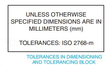
Figure 3: ISO 2768 tolerancing specified in the dimensioning and tolerancing block
On the other hand, in accordance with ISO 2768, general tolerances are specified in a general note, as illustrated in Figure 4.

Figure 4: ISO 2768 tolerancing specified in a general note
Table 1 below provides ISO 2768 general tolerances for linear dimensions. It’s important to note that sizes ranging between 0 mm and 0.5 mm are not included in Table 1. Dimensions below 0.5 mm must have a specified tolerance included on the dimension in a drawing. Any dimension that requires a tolerance that differs from the general tolerances listed in Table 1 must have a specific tolerance applied directly to the dimension in a drawing.

Table 1: Permissible tolerances for linear dimensions (mm)
Table 2 provides the ISO 2768 general tolerances for external radius/radii and chamfer dimensions. It’s important to note that sizes ranging between 0 mm and 0.5 mm are not included in Table 2.

Table 2: Permissible tolerances for external radius/radii and chamfer dimensions (mm)
Table 3 gives the ISO 2768 general tolerances for shorter side lengths of different angles or angular dimensions. It’s important to note that sizes ranging between 0 mm and 0.5 mm are not included in Table 3.

Table 3: Permissible tolerances for shorter side lengths of different angles or angular dimensions (mm)
