
Limit dimensions are a logical procedure that specifies tolerance directly by using dimensions provided for the upper and lower limits of a structure, object, or feature’s size. The maximum value which is the upper or high limit is usually placed above the minimum value or low limit, with both the high and low limit standing in place of any given dimension value.
Figure 1 below shows a hole that may not be less than 1.250 inches (i.e., 1.250″) and not greater than 1.251″.


Figure 1: Specifying the fit for an object through limit dimensions
Both 1.250 and 1.251 inches are the limits for the dimension, with a tolerance of 0.001″ as the difference between them (see Figure 2).
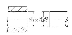
Figure 2: Limit dimensions
In similar manner, the shaft that is mating with the hole must have a dimension that is between the specified upper and lower limits of 1.248″ and 1.247″, respectively. The tolerance for the shaft is 0.001″ because the difference between the limits (i.e., 1.248″ and 1.247″) is .001″. Any shaft will fit inside any hole, interchangeably, because the minimum clearance is .002″.
In terms of metric units or dimensions, the lower and upper limits for the hole are 31.75 mm and 31.78 mm, respectively, and the difference between them (i.e., 0.03 mm) is the tolerance (see Figure 3). In addition to the hole, the specified limits for the shaft are 31.70 mm and 31.67 mm, and the tolerance or difference between them is 0.03 mm.

Figure 3: Limit dimensions in metric units
Parts or objects are not always toleranced if they are required to fit properly in an assembly or drawing, but are not required to be interchangeable. Figure 4 shows an example of objects that are not required to be interchangeable. Therefore, they have a noninterchangeable fit.

Figure 4: Noninterchangeable fit
