Category Archives: Technical & Engineering Drawings

How to Create Three-point Perspective Drawings

Three-point perspective drawing (sometimes called oblique perspective drawing) is the type of technical or engineering drawing in which none of the three main edges or principal faces (for e.g.: top, front, and side view) of the drafted object are parallel to the plane of projection or picture plane. The absence of edges that are parallel to the plane of projection sets up three different vanishing points, with one vanishing point for each edge. As a result, three vanishing points are always used in three-point perspective drawings.

The construction of three-point perspective drawings usually requires more time than two-point perspective drawings, and generally, at least a significant area of space is required on a drawing sheet in order to create three-point perspective drawings which are mostly used when certain effects are needed for visual illustration and simulation of objects such as tall structures and buildings.

In three-point perspective drawing, each picture plane or plane of projection is approximately perpendicular to the centerline of the cone of visual rays associated with a vanishing point—there are three vanishing points. When constructing a three-point perspective drawing on paper, imagine that the drawing sheet/paper is the picture plane (the actual plane on which the object or picture is drawn) and the object is behind the paper and placed in such a way that all the object’s edges are respectively at an angle to the object or picture plane.

There can be more than one center of vision (CV) on a three-point perspective drawing, and each CV represents a station point on the picture plane, with vanishing points P, Q, and R and connected lines drawn from each station point as shown in Figure 1 which also shows the center of view (CV) marked lightly with the object’s top view, plan view, and front view in the area or vicinity around it.

643_1

Figure 1: Illustration of the general procedure involved in constructing three-point perspective drawing of an object

Steps for creating three-point perspective drawings using the least amount of drawing space

You can create a three-point perspective by positioning three different vanishing points and determining the center of vision (CV) by constructing the individual perpendicular bisectors. To make the construction of three-point perspective drawings easier, place the object at the center of vision such that each of its edge lines recedes from their respective position on the object toward their respective vanishing point. You need significant drawing space, but regardless of any appreciable space you have, you should be able to estimate proportionate distances to create a three-point perspective drawing that is at least visually appealing.

The following steps can be taken to create any three-point perspective drawing using the least amount of space.

Step 1: Construct an equilateral triangle on your drawing sheet, big enough to cover as much area on the sheet as possible. Using each of the three corners of the equilateral triangle as one of three vanishing points, label each respectively as VPR (vanishing point right), VPL (vanishing point left), and VPV (vanishing point vertical). Use the necessary drawing instrument(s) to construct perpendicular bisectors of each of the three sides, and label their intersection at the center of the triangle as SP—meaning station point (see Figure 2).

643_2

Figure 2: Establishing three vanishing points (VPR, VPL, and VPV) and a station point (SP)

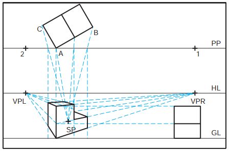
Step 2: After determining your views (top, front, side), construct a horizontal line to pass through the station point (SP), then mark the length of the object toward the left of SP, and mark the width of the object to the right of SP, thereby setting up a framework that can allow you to construct an object/picture in perspective as if the plan view has been turned by 45° to the picture plane line. Draw a line is parallel to line VPV-VPR as shown in Figure 3. This line will be your height measuring line which will help in constructing the height of the object from SP down toward the left along the measuring line as shown in Figure 3 which also shows numbers (1, 2) placed at intervals along each measuring line for indicating measurements (width, length, height) of the object’s features.

643_3

Figure 3: Establishing the length, width, and height of the object

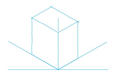
Step 3: Construct lines from points 1 and 2 (at the left of SP) to VPR, and construct a line from point 1 (at the right of SP) to VPL. The proceed to construct lines from points 1 and 2 on the height measuring line VPR to start forming outlines indicating the overall measurements of the object (see Figure 4). Your construction should establish the following points: the object’s lower-front corner (A), the object’s upper-right corner (B), the object’s upper-far corner (C), and the object’s upper-left corner (D), with the SP appearing as an upper-front corner of a box that is enclosing the object as shown in Figure 4.

643_4

Figure 4: Establishing the outline of the object

Step 4: Project the object’s upper-right corner (B) and upper-left corner (D) to VPV. Also project the object’s lower-front corner (A) to VPR and VPL, respectively, thereby forming intersections for points E and F which are the object’s lower-left and lower-right corners, respectively. The height of the front corner of the object is denoted by point G as shown in Figure 5 which illustrates the complete three-point perspective drawing of an object that has each surface parallel to one of the principal planes of the orthographic view and projecting to one of the three vanishing points.

643_5

Figure 5: A complete three-point perspective drawing

How to Create Two-point Perspective Drawings

Two-point drawing perspective drawing (sometimes called angular perspective drawing) is the type of technical or engineering drawing in which the drafted object is oriented at an angle to the projection plane and one set of parallel edges is vertical but has no vanishing point, while the other two sets of parallel edges have vanishing points.

Two-point perspective drawing is often used for illustrating buildings, dams, bridges, and large structures in civil, structural, and architectural drawings respectively. The two-point perspective drawing of an object and a small building are respectively shown in Figure 1.

635_1a

635_1b

Figure 1: Two-point perspective drawing of an object and a building, respectively

Generally, it is easier to create two-point perspective drawing for any object by:

  1. Drafting one of the edges of the object in the PP (picture plane) to make measurements directly from it.
  2. Inclining or positioning the object so that different faces or planes of the object are not equally inclined to the picture plane. For example, one angle can be inclined at 30° and the other at 60°.

Steps for creating two-point perspective drawings using The Plan View Method

There is another method for creating two-point perspective drawings, which is called Measuring Line Method, but this post presents the steps used in Plan View Method for two-point perspective drawings in. In the plan view method, the plan view of the object is positioned in such a way that its surfaces are inclined at an angle to the PP (picture plane) and one set of vertical parallel edges are not projected to a vanishing point, while the other two sets of vertical parallel edges are respectively projected to different vanishing points—i.e., the other two sets of edges each have a vanishing point.

Usually, one corner of the object is drawn on the picture plane from which projections are easily made to create the perspective view: the plan view is drafted and inclined at an angle to the picture plane, while the plane or face of the object that has the most graphic details is positioned along the axis that has the least angle.

The following steps can be taken to create any two-point perspective drawing using the Plan View Method:

Step 1: Draw the picture plane (PP) line horizontally around/near the top of the drawing paper, draw the horizon line (HL) horizontally around the middle of drawing paper, and lastly draw the ground line (GL) below the horizon line as shown in Figure 2.

635_2

Figure 2: Step 1

Step 2: Choose your plan view of the object and draw it in such a way that one corner is on the picture plane, has the only real length in the perspective view, and will be used to make direct measurements. As an example, Figure 3 shows one face of the object inclined at 30° to the picture plane with the other face inclined at 60°. But other sets of angles such as 15° and 75°, and 30° and 45° are also commonly used and can be used to create two-point perspective drawings. Usually, the side of the object that has most graphic details is drawn along the axis that is inclined at the least angle which is 30° in this example.

635_3

Figure 3: Step 2

Step 3: Draw the chosen profile view or front view of the object on the ground line (GL) and place the station point (SP) near it in such a way that the cone of vision (or bird’s eye view) is approximately 30°. To get this 30° cone of vision, start from the outermost corners of the plan view near the PP and draw two lines that intersect at a point and are 30° from each other as shown in Figure 4. In this example, the station point (SP) is centrally positioned below the plan view, but it can also be positioned at the right or left to get a different view of the object.

635_4

Figure 4: Step 3

Step 4: From the station point (SP), draw a line such that it is parallel to line A–B in the plan view and intersects PP (picture plane) at point 1 as shown around the top of Figure 5. Next, draw another line from SP such that it is parallel to line A–C in the plan view and intersects PP at point 2. At all times, the angle between line SP–1 and line SP–2 will/should always be 90° because they are respectively parallel to two main dimensions of the chosen plan view of the object. Proceed to draw a vertical line downward from point 1 and another vertical line downward from point 2 such that they both intersect HL (horizon line) at VPR (vanishing point right) and VPL (vanishing point left), thereby establishing two vanishing points, as is usually depicted on two-point perspective drawings.

635_5

Figure 5: Step 4

Step 5: As shown in Figure 6, draw a vertical line downward from A (on PP) to GL (ground line) to establish the measuring line for the perspective view. Next, make a horizontal projection of the height dimensions of the object from the chosen profile or front view to the established measuring line, and also make a horizontal projection of the height dimensions from the measuring line to VPR and VPL to create the respective perspective views of the front and side faces of the object.

635_6

Figure 6: Step 5

Step 6: Project inclined lines downward from corners B and C (of the chosen plan view) to the station point and mark the points where the projected inclined lines intersect PP (picture plane). From the points where the projected inclined lines intersect PP, draw vertical lines directly downward to GL (ground line). Next, mark the intersections between the projectors from the bottom corners of the object in the picture plane and the perspective lines from the measuring line to VPR (vanishing point right) and vanishing point left (VPL). These intersections define the bottom or rear plane of the object. Thicken the lines to produce visible edges of the object for the complete two-point perspective drawing, as shown in Figure 7.

635_7

Figure 7: Step 6, the complete two-point perspective drawing

How to Create One-point Perspective Drawings

One-point drawing perspective drawing is the type of technical or engineering drawing produced from linear perspective projection in which a set of construction rules are used to ensure that the lines of sight or projectors diverge away from their point of convergence (or vanishing point) as they approach an object’s plane of projection; but the same projectors (or imaginary lines or lines of sight) converge/meet at only one vanishing point. As a result, any one-point perspective drawing consists of only one vanishing point.

In one-point perspective drawing, the drawn object is oriented in such a way that two sets of the object’s principal edges are parallel to plane of the drawing (i.e., any imaginary flat surface parallel to the plane of the drawing) and a third set of principal edges is at right angle (i.e., perpendicular) to the plane of the drawing.

But the third set which is at right angle to the plane of the drawing also consists of parallel lines that would converge at a single vanishing point in perspective. Figure 1 shows an object drawn with one of its faces parallel to the plane of the drawing which is also known as the picture plane (PP) of the object. Depending on the type of drawing that needs to be produced, the chosen face can be placed perpendicular or at right angle to the plane of the drawing (PP), instead of being parallel to it.

627_1

Figure 1: One-point perspective drawing

As indicated by some of the straight blue construction lines that run from the lower to the upper part of the drawing, as shown in Figure 1, the piercing points of eight main edges (of the drawn object) perpendicular to the picture plane (PP) are located by extending them to PP and thereafter projecting them downward to the level of the lines projected over from the elevation view.

To locate the vanishing point (VPR) of the lines, draw an imaginary line of sight or visual ray from the station point (SP) and make it parallel to the lines. The center of vision (CV) is the location of the vanishing point of all lines that are perpendicular to the picture plane (PP). The eight piercing points of the drawn object can be easily connected with the vanishing point (also known as “the center of vision”) in order to locate or find the focal point or directions for the perspective lines of the eight edges.

Horizontal lines have to be constructed from the endpoints of one of the drawn object’s edges in the top view and at any chosen angle (for example, 45°) in order to construct the actual lengths of the edges of the object along the perspective lines.

Steps for creating one-point perspective drawings using the Plan View Method

In the Plan View Method, the depth dimensions of the drawn object are defined or illustrated by projecting construction lines from the plan view (or top view) to an essential point called the station point. The following steps should be taken to create any one-point perspective drawing using the Plan View Method:

Step 1: First, construct or draw a thin long horizontal line across the center of the whole width of the drawing area or paper, and proceed to draw two other thin long horizontal lines across the width and somewhere around the upper and lower parts of the drawing area or paper. These lines are the locations of the picture plane (PP) near or around the top, the horizon line (HL) around the middle, and the ground line (GL) near or around the bottom of the drawing area to produce a view of the object from above. Each line should be labelled as shown in Figure 2.

627_2

Figure 2: Step 1

Step 2: Draw the top or plan view of the object on the PP (picture plane) line to create a perspective view that will as be as close to the full size of the object, as possible. Then proceed to draw the profile view or right side view near the right edge of the drawing area/paper, with the base of the right side view positioned on the GL (ground line). Set the location for the station point (SP) by constructing a distance that is beneath the PP and is two or three times the width of the object, and closer to the right of the center as shown in Figure 3.

627_3

Figure 3: Step 2

Step 3: Project the width of the object’s top or plan view vertically downward to the GL (ground line) in order to construct or draw the front face of the one-point perspective drawing or view. Then, project the height dimensions of the object from the right side view horizontally across the drawing area. Since the object’s front plane is parallel to the picture plane (PP), its true size can be drawn with the aid of the width dimensions projected from the plan view. Construct a vertical line from the SP (station point) upwards to the HL (horizon line) to define and set up the position of the vanishing point (VP) as shown in Figure 4.

627_4

Figure 4: Step 3

Step 4: To define and position the object’s depth distance(s) in the perspective view, go to the plan view and project all the object’s rear or back corners to the SP (station point). Notice the points where the projectors from the rear corners cross the PP (picture plane). Drop vertical lines downward from those points to the GL (ground line). Move to the front view and draw lines from the object’s corners to the VP (vanishing point) on the HL (horizon line). The front view forms part of the one-point perspective drawing as shown in Figure 5.

627_5

Figure 5: Step 4

Step 5: The depth points for any completed one-point perspective drawing is defined and positioned with the help of the intersections formed when vertical projectors from the PP (picture plane) line intersect with projectors from the front view to the VP (vanishing point). As illustrated in Figures 6 and 7, draw a line between points A and B, B and C, C and D, and D and E, to produce the rear or back plane of the object which can be clearly seen.

627_6

Figure 6: Step 5

627_7

Figure 7: Completed one-point perspective drawing

To complete the one-point perspective drawing of the object as shown in Figure 7 above, draw lines from the front corners to the back corners of the object along the projectors to the VP (vanishing point). It may be important to note that in perspective drawing, dash lines do not have to be included for hidden features, except to enhance visualization.

Perspective Drawing Concepts & Principal Components

Perspective drawing is the best form for representing real—not abstract or ideal—objects, features, or structures due to the pictorial illustration it provides in the most realistic way by giving representations of objects as they appear smaller the further away they are from any observer’s eye. The perspective projection lines (i.e., lines of sight from the observer’s eye) are parallel to the principal orthographic planes and come together, meet, or converge at a point called the “vanishing point”.

Perspective projection is sometimes called perspective view or perspective drawing, or simply “perspective”: the lines of sight in perspective projection start at a single point (the observer’s eye) and move towards an object or converge at a single point away from an object.

Definition of perspective drawing

Perspective projection is the type of projection in which the projectors or lines of sight originate from the same point (called point of convergence or vanishing point) and diverge away from each other the more they approach an object’s plane of projection, thereby resulting in illustrations or drawings of objects that appear smaller the more their distance increases away from the vanishing point, eyes of the observer, or eyes of the projector.

Types of perspective drawing

There are three types of perspective drawing or drawing techniques which are named according to the number of vanishing points used in each type.

  • One-point or parallel perspective drawing: This type of perspective drawing has only one vanishing point and is mostly used to illustrate the interior parts or features of rooms in buildings.
  • Two-point or angular perspective drawing: This type of perspective drawing has two vanishing points. It is the most popular type of perspective drawing and mostly used to illustrate the exterior parts of houses, small buildings, construction projects, and sometimes, machine components as well.
  • Three-point perspective drawing: This type of perspective drawing has three vanishing points and is usually employed in illustrating objects that are tall or have great vertical measurements; for example, skyscrapers and tall or multi-story buildings.

Perspective drawing basic concepts & principal components

The two principal components of any type of perspective drawing are: 1. the observer’s eye (i.e., the eye of the person who is viewing an object) and 2. the position of the person in relation to the position of the object.

The observer’s eye level is called the horizon line (HL) which is a line that is established in the front or elevation view as shown in the figure below.

619_1

Figure: Principal components of perspective drawings

The position of the observer in relation to the position of the object is called the station point (SP) which is a location or position that is established in relation to the top view or plan of the object.

The position or location of the station point dictates the proximity or closeness of the observer in relation to the object and the angle at which the observer is making a projection or viewing the object.

The line on which the object is stationed or rests is called the ground line (GL), while the plane of projection or picture plane (PP) is the surface, media, drawing sheet, or computer on which the object is being projected. The picture plane can be positioned anywhere between the observer and the object; it can also be positioned or located beyond the object.

The three vanishing points mentioned in the three different types of perspective projection are respectively called:

  • vanishing point right (VPR)
  • vanishing point left (VPL), and
  • vanishing point vertical (VPV)

The vanishing point right (VPR) is the point at which projection or parallel lines that are receding from an observer appear to converge to the right. The vanishing point left (VPL) is the point at which the projection or parallel lines that are receding from an observer appear to converge to the right. The vanishing point vertical (VPV) is the point used in three-point perspective to illustrate the vertical orientation and show how the parallel lines that are receding from an observer appear to converge above or below the object.

Oblique Drawing: Three Methods of Oblique Drawing

Oblique drawing is the type of pictorial drawing in which the front feature or surface of an object is parallel to the plane of projection and the imaginary projector or lines of sight are inclined at an angle to the plane of projection but still parallel to each other. The viewer of an oblique drawing can be able to see three faces of an object, and generally see objects in 3D, but with some distinct features.

The front face (usually the face that has the most details), along with any surface that is parallel to the front face, is illustrated in its real or actual shape and size, while  the other two planes or faces are inclined at an angle.

Oblique drawing is suitable for illustration if the orientation or alignment of one of the main faces of an object needs to be flat. This orthographic flat face that is chosen should have the most curves and circles—if present on the object—because these features are more difficult to draw on any other surface that is inclined at an angle.

Three methods of oblique drawing are cavalier oblique projection, cabinet oblique projection, and general oblique projection:

1. Cavalier oblique projection

Cavalier oblique projection is a method in which the lines that are receding from the chosen flat surface, are drawn according to the real or actual size—i.e., full scale—usually, with one of the receding lines drawn at an angle of 45° from the horizontal axis, thereby providing a viewing angle of 45°.

Cavalier oblique projection or cavalier drawing is not very appropriate for long objects if the long axis is perpendicular to the front face. The reason, in most cases, is due to the full scale usually applied on the receding line or axis; this makes the object look somewhat distorted. Cavalier oblique projection is very appropriate for clearly illustrating objects that have a width that is bigger that the depth—in other words, the depth is smaller than the width. Figure 1 illustrates the cavalier oblique drawing of two different objects.

615_1

Figure 19_3Cavalier drawing of different objects

Figure 1: Cavalier oblique drawing

2. Cabinet oblique projection

In cabinet oblique projection, the object is also drawn or illustrated with a receding angle of 45°, but the receding line or axis is half scale or size instead of full scale or size which is characteristic of cavalier oblique projection.

Cabinet oblique projection is very appropriate for clearly illustrating objects that individually have a depth that is greater than their width. Cabinetmakers usually draft or draw their cabinet designs using cabinet oblique projection. The cabinet oblique drawing of two different objects is shown in Figure 2.

615_2

Figure 20_3Cabinet drawings of different objects

Figure 2: Cabinet oblique drawing

3. General oblique projection

General oblique projection is usually employed at any other angle that is not 45°, and the scale used on the receding line or axis is different from the scale used in cavalier and cabinet oblique projection or drawing, respectively.

Although any angle can be used, the angles mostly used for general oblique projection or drawing includes 30°, 45°, and 60°. Any of these angles can be used together with any scale between half size and full size. Figure 3 shows the general oblique drawing of an object.

615_3

Figure 3: General oblique drawing

Exploded Pictorial Drawing in Technical & Engineering Drawings

In order to provide a broad and much more realistic view and understanding of equipment or product parts and mechanisms, an exploded assembly or exploded pictorial drawing is often used to show the relationship between different parts. This type of drawing—i.e., exploded pictorial drawing—is commonly used in parts of equipment manuals, catalogs, and assembly instructions as shown in Figure 1.

612_1

Figure 1: An exploded assembly without a list and also without parts’ numbers enclosed in balloons

An exploded pictorial drawing or an exploded assembly can be defined as any technical or engineering drawing that consists of a collection, an assemblage, or a group of different parts considered as a whole, with each part drawn using the same axonometric projection method.

Axonometric projection is a type of expression of orthographic projection that is well suited for illustration purposes such as exploded pictorial drawing or exploded assembly. In axonometric projection, the lines of sight or parallel projectors are directed perpendicularly towards any plane of a 3-D object that is tipped or rotated about one or more of its major axes (x, y, and z) to show different sides (top, side, and front views), and the projection is usually expressed in a single view with some foreshortened dimensions that are easy to visualize.

Axonometric projection is usually employed in producing three different types of engineering drawing: isometric, dimetric, and trimetric drawing, respectively. Any of these three pictorial drawing methods can be used to construct exploded pictorial drawings or exploded assemblies, but 3-D models and isometric drawings are most commonly used.

When using a 3-D model, an isometric drawing, a dimetric drawing, or a trimetric drawing to produce an exploded assembly, the most important thing to do is select the viewing direction or position of line of sight that would illustrate most of the details of the assembly.

The lines used in exploded assemblies should always be drawn parallel to the axis lines of the drawing, no matter the type of drawing method used. The clearest illustration can be made by ensuring that there are gaps where connection lines individually intersect any mating feature and part to which it applies, as shown in Figure 2.

612_2

Figure 2: An exploded assembly without a list and also without parts’ numbers enclosed in balloons

Some organizations, companies, institutions, or schools prefer to illustrate parts close together, but as clearly as possible without using connection lines. Depending on what an exploded isometric assembly needs to be used for, the parts on it can be drawn without identification as shown in Figures 1 and 2 above, or they can be identified using balloons. A balloon is a circle that encloses a number and is used to identify a part or feature.

Although identification on an exploded pictorial drawing commonly uses circles as balloons with numbers inside, some organizations, companies, or institutions prefer using numbers without circles. A leader line is commonly used to connect each balloon to its related part, and the balloon identification number correlates to the same number used to identify the part in a parts list (PL) which tabulates/lists and identifies all the parts and materials in an exploded assembly, as shown in Figure 3.

612_3a

612_3b

Figure 3: An exploded assembly with balloons, parts list, and assembly notes

It is not necessary to draw all parts of an assembly in their final positions when using CADD or any other technical or engineering drawing software. Each part can be drawn as needed, by placing construction lines for the connection lines; after completing all parts, each part can be moved around as needed in order to construct the final layout.

Types of Isometric Drawing

Isometric drawing is one of the different types of engineering drawing that are produced from axonometric projection, but all the angles between the axonometric axes are equal. To produce an isometric drawing from axonometric projection, you have to orientate the object you want to draw so that its principal axes or edges are equally inclined with the plane of projection, and are thereby equally foreshortened.

If you orientate an object—for example, a cube—by equally inclining the principal axes, then the edges of the object will be projected in such a way that they are the same and have equal angles (i.e., 120°) with each other, and the receding axes are inclined or drawn at 30° from the horizontal as shown in Figure 1.

609_1

Figure 1: Isometric drawing showing the edges of a cube with equal angles of 120° and receding axes inclined at 30° to a horizontal datum or axis

The isometric axes can be used to make measurements during dimensioning. Any line that is parallel to any of the isometric axes is called an “isometric line”. Any plane that is parallel to any of the faces or planes of an object is called an “isometric plane”. It may be important to point out that the angles in the isometric projection of a cube can be either 120° or 60°.

Any line that is not parallel to any of the isometric axes is called a “non-isometric line” (see Figure 2 below). Non-isometric lines are lines that are constructed or drawn at angles not usually employed in isometric drawing. Thus, the lines are not equally foreshortened.

609_2

Figure 2: Non-isometric lines and edges

Basically, there are three types of isometric drawing:

1. Regular axis isometric drawing

Figure 3 shows the top of an object from a position that usually illustrates the regular axis form of isometric drawing. This presentation which shows the top of an object is the most common form generally applied to all objects in isometric drawing. Objects can be viewed from either side when using regular axis isometric drawing.

609_3

Figure 3: Regular axis isometric drawing

2. Reverse axis isometric drawing

The main–and probably only—difference between reverse axis and regular axis isometric drawing is that, in reverse axis, you can view the bottom of an object but not the top, and the 30° axis lines are constructed downward from the horizontal datum/axis, instead of upward. Figure 4 shows a reverse axis isometric drawing.

609_4

Figure 4: Reverse axis isometric drawing

3. Long-axis isometric drawing

Long-axis isometric drawing is normally used to illustrate long objects; for example, shafts. Figure 5 shows a long-axis isometric drawing.

609_5

Figure 5: Long-axis isometric drawing

Concluding remark

The most appropriate type of isometric drawing that should be chosen is the one that gives very rich or complete details and represents any object in the best possible way possible. For example, if people usually view an object from below, then reverse axis isometric drawing would be the most befitting for the object.

Form Tolerances That Are Used in Controlling the Form of Geometric Shapes

Form tolerances are used to define or determine a zone for any dimensioned part or feature, or a part or feature’s line elements, or a part or feature’s derived median plane by using controlled concepts and techniques of dimensioning and tolerancing usually employed in controlling the form of geometric shapes.

Form tolerances are not related to datums but can be applied to datum features, single parts or features, or the components of single parts or features. Different form tolerances are generally used to control the form of geometric shapes:

  • Straightness
  • Flatness
  • Circularity
  • Cylindricity

When a form geometric tolerance is applied to datum features, it is specified on the technical or engineering drawing by attaching the datum feature symbol directly to the leader associated with the feature control frame or the form control feature control frame.

1. Straightness

Straightness is a form tolerance that indicates a condition whereby a component or element of a feature’s surface or axis is straight or in a straight line. Straightness tolerance defines and determines or sets a zone in which any axis or surface element of a feature must be positioned and occupy.

Axis or surface element straightness is usually specified on technical and engineering drawings by positioning the feature control frame below any diameter dimension and placing a diameter symbol at the front end of the required geometric tolerance. This is usually employed in fixing a cylindrical tolerance zone.

Unit straightness, also known as “straightness per unit of measure”, can be used in combination with a straightness specification over the whole length of a feature or part. The purpose is to prevent any abrupt surface variation within a comparatively short length of the feature or part.

In regard to the straightness on the sizes of non-cylindrical parts or features, straightness can be applied regardless of feature size (RFS) and regardless of a feature’s maximum material condition (MMC). When straightness is applied to any of these conditions, it must be ensured that the related median plane of the feature lies within two parallel planes that are placed apart from each other by a distance equal to the specified geometric tolerance zone.

When straightness is applied to a flat surface or area, the straightness geometric tolerance restrains single line elements to only one or two directions on the part or feature’s surface.

Apart from straightness over a unit length (i.e., unit straightness) and straightness over a whole length, straightness can also be applied over a portion or limited length of a part or feature by positioning a chain line beside an essential view at the desired straightness length, with the length of the chain line dimensioned and the feature control frame connected to the chain line. Straightness over a portion can be applied to a flat feature or cylindrical feature or part.

2. Flatness

Flatness is a form tolerance that indicates the condition of a surface or area that has all components or elements in one plane. Flatness tolerance zone defines and determines or sets the distance between two parallel planes in which a surface element of a feature must be positioned and occupy. All points of a required surface must lie within the limits of the specified flatness tolerance zone. The smaller the flatness tolerance zone, the flatter the surface will be. It may be important to point out that size tolerance must be greater than flatness tolerance when the surface is related with a size tolerance.

Flatness tolerance can be applied to a size dimension by positioning the feature control frame below the dimension of the part or feature that needs to be controlled, but the derived median plane of the part of feature must be located within two parallel planes that have a distance apart which is equal to the specified flatness geometric tolerance.

Specific area flatness refers to flatness tolerance that is applied to only a specific area of a surface. The procedure involved in specific area flatness is mostly applied on any large cast surface that must be flat in a comparatively small area.

Unit flatness tolerance is appropriate for controlling the flatness of a given surface area in order to put any abrupt surface variation under control in a small area of a part or feature. The specification for unit flatness can be used either alone or in combination with a total tolerance. Total tolerance must be greater than unit tolerance which can be determined by using a rectangular, square, or circular unit area.

3. Circularity

Circularity is a form tolerance characterized by any cross section that is orientated perpendicular to the axis of a cone or cylinder, or through the center of a sphere. Circularity geometric tolerance can be formed by using two concentric circles and placing a surface within them. It may be important to note that size tolerance must be greater than circularity tolerance or “circularity geometric tolerance”.

When circularity tolerance is applied to a sphere, the circularity geometric tolerance is constituted by using two concentric circles formed by a plane that must pass through the center of the sphere, with all the points on the surface positioned within the circularity tolerance zone.

Size tolerance must be greater than circularity tolerance, but this is not applicable to any “free state variation” that occurs alongside circularity. Circularity tolerance can be greater than size tolerance when parts or features are subject to free state variation. Free state variation is an undesirable change or distortion of a part or feature after forces applied during manufacturing have been removed. A part or feature can be distorted after forces applied during manufacturing have been removed.

4. Cylindricity

Cylindricity is a form tolerance that is not referenced to a datum and is usually considered irrespective of the size of the concerned part or feature. Cylindricity is characteristic of any tolerance zone that consists of two perfectly concentric cylinders in which a required area or surface must be positioned or occupy. Cylindricity includes straightness, circularity, and the taper of a cylindrical part or feature.

How Limit Dimensions Are Used to Specify Fits on Drawings

Limit dimensions are a logical procedure that specifies tolerance directly by using dimensions provided for the upper and lower limits of a structure, object, or feature’s size. The maximum value which is the upper or high limit is usually placed above the minimum value or low limit, with both the high and low limit standing in place of any given dimension value.

Figure 1 below shows a hole that may not be less than 1.250 inches (i.e., 1.250″) and not greater than 1.251″.

603_1a

603_1b

Figure 1: Specifying the fit for an object through limit dimensions

Both 1.250 and 1.251 inches are the limits for the dimension, with a tolerance of 0.001″ as the difference between them (see Figure 2).

603_2

Figure 2: Limit dimensions

In similar manner, the shaft that is mating with the hole must have a dimension that is between the specified upper and lower limits of 1.248″ and 1.247″, respectively. The tolerance for the shaft is 0.001″ because the difference between the limits (i.e., 1.248″ and 1.247″) is .001″. Any shaft will fit inside any hole, interchangeably, because the minimum clearance is .002″.

In terms of metric units or dimensions, the lower and upper limits for the hole are 31.75 mm and 31.78 mm, respectively, and the difference between them (i.e., 0.03 mm) is the tolerance (see Figure 3). In addition to the hole, the specified limits for the shaft are 31.70 mm and 31.67 mm, and the tolerance or difference between them is 0.03 mm.

603_3

Figure 3: Limit dimensions in metric units

Parts or objects are not always toleranced if they are required to fit properly in an assembly or drawing, but are not required to be interchangeable. Figure 4 shows an example of objects that are not required to be interchangeable. Therefore, they have a noninterchangeable fit.

603_4

Figure 4: Noninterchangeable fit

Groups and Classes of Fits Between Mating Parts in Technical & Engineering Drawings

In ASME  B4.1 (Preferred Limits and Fits for Cylindrical Parts), the American Society of Mechanical Engineers provides three general groups of limits and fits between mating parts: running and sliding fits, locational fits, and force fits. ASME B4.2 (Preferred Metric Limits and Fits) provides metric limits and the general types or groups of fit between mating parts: clearance fit, interference fit, and transition fit.

The three general groups of fits (running and sliding fits, locational fits, and force fits) can be broken down into their respective classes, usually designated by the following letter symbols:

  • RC: Running, or Sliding Clearance Fit
  • LC: Locational Clearance Fit
  • LT: Transition Clearance, or Interference, Fit
  • LN: Locational Interference Fit
  • FN: Force, or Shrink, Fit

These letter symbols are usually placed side by side with numbers to denote the class of each group of fit—for example, FN3 denotes a class 3 (heavy drive fits) of the force fit group of fits. Generally, the main groups of fits between mating parts in technical and engineering drawings are:

1. Running and Sliding Fits (RFC)

The intention of using running and sliding fits is to provide the same type of running performance with suitable lubrication allowance for all range of sizes. The classes of running and sliding fits are as follows:

  • RC1 (close sliding fits): The intention for using these fits is to accurately locate parts that must assemble without moving or turning easily or in a perceptible way.
  • RC2 (sliding fits): The purpose of these fits is to accurately locate parts but with more maximum clearance than class RC1. The mating parts for these fits move and turn easily; however, there is no intention to have them running freely. In other words, the intention of the fits is not to run freely, but to move and turn freely and locate parts accurately.
  • RC3 (precision running fits): This class of running and sliding fits is best suited for precision work and the fits are expected to run freely at light journal pressures and slow speeds. However, it’s important to note that they are not suitable for conditions have appreciable temperature differences.
  • RC4 (close running fits): These fits are mainly used for running fits on accurate machinery with moderate journal pressures and surface speeds in situations where accurate location of parts and minimum moving and turning or play are desired.
  • RC5 and RC6 (medium running fits): These two classes of fits are intended for circumstances involving heavy journal pressures, or high running speeds, or circumstances that involve both heavy journal pressures and high running speeds.
  • RC7 (free running fits): These fits are intended for conditions that are not accurate or accuracy is not essential or the main goal. In addition, they are intended or suitable for situations in which high running speeds, large temperature variations, or heavy journal pressures are expected.
  • RC8 and RC9 (loose running fits): These fits are suitable for situations in which wide commercial tolerances may be essential or a necessity, together with an allowance, on external parts or structural members.

2. Locational Fits (LC, LT, and LN)

The purpose for using locational fits is to determine only the location of mating parts. Like any interference fit, locational fits provide accurate location; they also provide some freedom of location like any clearance fit does. The classes of locational fits are as follows:

  • LC (locational clearance fits): This class of locational fits is suitable for locating members or parts that are usually stationary but can also be assembled or disassembled.
  • LT (locational transition fits): These fits are somewhere halfway or in between interference fits and clearance fits, and are applied to situations where accurate location of parts is important but a little interference or clearance is allowable or permissible.
  • LN (locational interference fits): This class is a perfect fit for situations that demand accuracy of location for members or parts that require alignment and rigidity without any particular requirements for bore pressure. Locational interference fits are not intended for members or parts that have been designed to transmit frictional loads from one member or part to another due to tightness of fit—but force fits are suitable for conditions requiring tightness of fit to ensure members or parts perform according to design!

3. Force Fits (FN)

Force fits (or shrink fits) consist of a peculiar kind of interference fit that usually maintains constant bore pressures throughout its variety or range of sizes and has an interference that varies almost directly with diameter. These classes of force fits are as follows:

  • FN1 (light drive fits): This class of force fits produces more or less permanent assemblies and requires light assembly pressures. Light drive fits are suitable for long fits or thin sections, and suitable in external cast iron members and also for shrink fits or parts that can be highly stressed.
  • FN2 (medium drive fits): These fits are almost the tightest fits that can be found, and they are widely employed on high-grade cast iron external parts or members. Medium drive fits are intended and suitable for shrink fits or ordinary steel parts on light parts or sections.
  • FN3 (heavy drive fits): This class is intended for shrink fits or heavy steel parts in medium sections.
  • FN4 and FN5: These two classes of force fits are suitable for members or parts that can be subjected to high stress levels, or shrink fits in which the required amount of heavy pressing forces is impractical.

Types of Fits Between Parts in Technical & Engineering Drawings

A fit in technical and engineering drawings—and even architectural drawing—is the range of constriction (i.e., tightness) or freedom from restraint (i.e., looseness) due to the tolerance(s) and allowance(s) in parts or objects that are being mated together.

The loosest fit (also called maximum clearance) refers to any situation whereby the smallest internal part (usually a shaft) is bordered or surrounded by the largest external part (usually a hole), as shown in Figure 1(a). Figure 1(b) shows the tightest fit (also called minimum clearance) which refers to any situation whereby the largest shaft is in the smallest hole. The allowance is the difference between the smallest allowable hole size and the largest allowable shaft size—for example, 0.002″ (i.e., 0.002 inches) shown in Figure 1(b).

597_1

Figure 1 (a) Loosest fit and (b) Tightest Fit

The following three types of fits usually applied between mating parts in technical and engineering drawings:

1. Clearance fit

A clearance fit refers to any situation whereby an internal mating part fits into an external mating part in such a way that there is still available clearance, space, or allowance between the mating parts. Figure 2 shows the largest shaft (which has a diameter of 1.248″) and the smallest hole which has a diameter of 1.250″, with a minimum clearance, space, or allowance of 0.002″ between the mating parts. It may be important to note that, in clearance fit, the clearance or allowance is always positive.

597_2

Figure 2: Clearance fit

2. Interference fit

An interference fit refers to any situation whereby an internal mating part is larger than an external mating part but to only such an extent that force must be used to fit the mating parts together. Figure 3 shows the smallest shaft (which has a diameter of 1.2513″) and the largest hole which has a diameter of 1.2506″, with the interference of metal between the mating parts set at not less than 0.0007″. The interference for the largest shaft and smallest hole is 0.0019″. It may be important to note that, in interference fit, the clearance or allowance is always negative.

597_3

Figure 3: Interference fit

3. Transition fit

A transition fit refers to any situation whereby there is either a tight clearance or interference. Figure 4 shows the smallest shaft (which has a diameter of 1.2503″) fitting into the largest hole which has a diameter of 1.2506″. However, the largest shaft (which has a diameter of 1.2509″) must be force into the smallest hole which has a diameter of 1.2500″.

597_4

Figure 4: Transition fit

4. Line fit

Line fit is used occasionally or in certain cases—but not always—to provide or indicate limits that are specified to help achieve clearance or surface contact aims of drafting when mating parts are assembled together.

Limit dimensions are often used to specify tolerance by providing dimensions for the upper and lower limits of the features of an object or its size. A maximum or high limit/value is placed above a minimum or low limit/value in place of a particular dimension value.

Specified and Unspecified Meter Tolerance Applications in Technical/Engineering Drawings

A previous post provided information about how specified and unspecified inch dimensioning and tolerances are applied in a general note or in the title block of technical and engineering drawings. The same strategy does not apply to metric dimensioning because metric dimensions don’t have trailing zeros attached to or included beside them.

ISO 2768 standard (or the General Tolerances developed by ISO) regulates metric tolerancing, and the ISO 2768 standard on tolerancing is based on the size of drawing or object features, with small feature sizes having closer tolerances and larger feature sizes having larger tolerances. Four classes of size tolerances are usually applied to drawings, and each class has its abbreviation in parentheses:

  • fine ( f)
  • medium (m)
  • coarse (c), and
  • very coarse (v)

Any institution, school, or company can select the class of size tolerance that can help achieve its goals or objectives. For instance, a company that manufactures different equipment and precision parts can employ the medium class (m) for general metric tolerances. Figure 1 shows a specified metric dimension and how a tolerance value is placed beside it.

594_1

Figure 1: A specified metric dimension and tolerance value placed beside it  

Figure 2 below shows how an unspecified metric dimension is placed in a dimensioning and tolerancing title block or general note.

594_2

Figure 2: An unspecified metric tolerance placed in a title block or general note

In accordance with ISO 2768, general tolerances are specified in the dimensioning and tolerancing block, as illustrated in Figure 3.

594_3

Figure 3: ISO 2768 tolerancing specified in the dimensioning and tolerancing block

On the other hand, in accordance with ISO 2768, general tolerances are specified in a general note, as illustrated in Figure 4.

594_4

Figure 4: ISO 2768 tolerancing specified in a general note

Table 1 below provides ISO 2768 general tolerances for linear dimensions. It’s important to note that sizes ranging between 0 mm and 0.5 mm are not included in Table 1. Dimensions below 0.5 mm must have a specified tolerance included on the dimension in a drawing. Any dimension that requires a tolerance that differs from the general tolerances listed in Table 1 must have a specific tolerance applied directly to the dimension in a drawing.

594_5

Table 1: Permissible tolerances for linear dimensions (mm)

Table 2 provides the ISO 2768 general tolerances for external radius/radii and chamfer dimensions. It’s important to note that sizes ranging between 0 mm and 0.5 mm are not included in Table 2.

594_6

Table 2: Permissible tolerances for external radius/radii and chamfer dimensions (mm)

Table 3 gives the ISO 2768 general tolerances for shorter side lengths of different angles or angular dimensions. It’s important to note that sizes ranging between 0 mm and 0.5 mm are not included in Table 3.

594_7

Table 3: Permissible tolerances for shorter side lengths of different angles or angular dimensions (mm)

Specified and Unspecified Inch Tolerances in Technical & Engineering Drawings

Except for reference dimensions, maximum dimensions, minimum dimensions, or stock size dimensions, all other types of dimensions on technical and engineering drawings have a tolerance.

Tolerance can be illustrated or identified in the dimensioning and tolerancing block. They can also be indicated by using a general note or applied directly to dimensions. Figure 1 shows how tolerance is applied directly to a dimension expressed in inches. This type of tolerance is called a specified inch tolerance.

591_1

Figure 1: Specified inch tolerance

Figure 2 shows an inch dimension that has no specified tolerance. Any inch dimension that doesn’t have a specified tolerance has what is called an unspecified tolerance, and thus has a relationship with general tolerances.

591_2

Figure 2: Unspecified inch tolerance

Generally speaking, all dimensions in technical and engineering drawings have tolerances, and general tolerances are illustrated in a general note or in the dimensioning and tolerancing block of a drawing. Figure 3 shows a dimensioning and tolerancing block which is usually placed near the title block or as an element of the title block.

591_3

Figure 3: Tolerances indicated in the dimensioning and tolerancing block

The dimensioning and tolerancing block consists of the general tolerance for:

  • one-place dimensions, such as 4.7±0.1
  • two-place dimensions such as 4.70±0.01
  • three-place dimensions such as 4.700±0.001, and
  • four-place dimensions such as 4.7000±0.0001.

It may be important to note that the tolerance for unspecified angular dimensions is ±30′. Figure 4 shows how general tolerances are specified in a general note.

591_4

Figure 4: General tolerances specified in a general note

Alternatively, general tolerance specifications can be provided in the dimensioning and tolerancing block by using X to represent the number of decimal places. Figure 5 shows a title block with a dimension and tolerancing block that uses:

  • X to refer to the tolerance applied to one-place decimal inch dimensions
  • XX to refer to the tolerance applied to two-place decimal inch dimensions or decimals, and
  • XXX to refer to the tolerance applied to three-place decimal inch dimensions.

591_5

Figure 5: A title block with a dimension and tolerancing block

Using the dimensioning and tolerancing block shown in Figure 5 as an example, the tolerances of the inch imensions are as follows:

  • 4.700 has 0.XXX±0.001 applied; 4.700±0.001, tolerance equals 0.002.
  • 4.70 has 0.XX±0.01 applied; 4.70±0.01, tolerance equals 0.020.
  • 4.7 has 0.X±0.020 applied; 4.7±0.020, tolerance equals 0.040.
  • 30° has angles ±0.5° applied; 30°±0.5°, tolerance equals 1°.

Inch dimensions that require tolerances that differ from the general tolerances provided in the general note or dimensioning and tolerancing block have to be specified on the dimension in a drawing. Such dimensions, if specified or indicated, are known as specific tolerance dimensions, usually indicated with plus–minus dimensioning limits as shown in Figure 6.

591_6

Figure 6: Specific tolerance dimensions indicated together with plus–minus dimensioning limits

A specific tolerance relates to a specific dimension on a drawing and has a tolerance that differs from the general tolerance indicated in a general note or the tolerance block.

Baseline Dimensioning

Baseline dimensioning is a popular technique mostly used in dimensioning mechanical or machine parts. In baseline dimensioning, each dimension that is applied to a feature on a drawing has its origin taken from a common datum, axis, surface, or center plane. Figure 1 shows how dimensioning is made from a common datum.

588_1

Figure 1: Baseline dimensioning from a common datum

It is less likely for tolerance buildup to occur when using baseline dimensioning; on the other hand, tolerance buildup is more likely to occur when using chain dimensioning. Baseline dimensioning is employed in technical and engineering drawings when the location or size of the features of a drawing need to be taken with reference from a common plane or datum and tolerance buildup or accumulation needs to be avoided. Because each dimension in baseline dimensioning is independent, there possibility for tolerance buildup to occur is less.

Figure 2 shows the symmetrical symbol and how baseline dimensions can be placed symmetrically about a center plane, with the baseline dimensions originating from the center plane of the part of a drawn object or drawing.

588_2

Figure 2: Baseline dimensioning, with baseline dimensions placed symmetrically about the center plane of the part of a drawn object

The symmetrical symbol in Figure 2 is placed on the centerline above and below the feature and used to illustrate that both sides of the portion of an object are symmetrical. Wherever a drawing is broken or part of it is cut, a short break line is used to indicate the break or cut.

Although it is common practice for breaks to be made on especially large parts, they should be avoided altogether whenever possible. Drafters and professionals usually prefer to make an entire view on a larger sheet.

Chain Dimensioning Application

Chain dimensioning is a technique in which dimensioning is applied from one feature of an object or drawing to the next feature of the same object or drawing. Therefore, chain dimensioning is also called point-to-point dimensioning: the location or placement of each successive dimension(s) is dependent on the location or placement of the previous dimension(s).

Chain dimensioning should be used with caution, if not the tolerance of each dimension could build up on the next dimension and lead to tolerance stacking or tolerance buildup which is not good for drawings. Figure 1 shows the standard mechanical drafting practice of locating or placing an overall dimension (i.e., 75) and leaving any one of the intermediate dimensions blank (i.e., the space beside dimensions 25 and 25).

585_1

Figure 1: Chain dimensioning

The overall dimension is usually placed alone, independently of the placement or location of the other dimensions. Certain levels of tolerance buildup are unacceptable especially when the overall dimension is decisive in a drawing.

It’s advisable to omit either one intermediate dimension or the overall dimension. There can be an exception to this rule whenever a dimension is provided only as reference. The reference dimension in a drawing is usually enclosed in parentheses. Figures 2(a) and (b) show the overall dimension of an object as a reference.

585_2

Figure 2(a) and (b): Examples of reference dimension and reference dimension symbol

Dimension Line Spacing

The dimension lines used in technical and engineering drawings are usually drawn parallel to the features of the object, shape, or structure that is being dimensioned in a drawing.

Dimension lines should be placed in such a way that they are at an unvarying, consistent, or uniform distance from the object, shape, or structure that has been drawn and is being dimensioned; all other dimension lines that come after the first dimension line should be equally spaced.

The first dimension line should be placed at a minimum distance of 0.375 inches or 10 mm away from a feature of the object, shape, or structure and the second dimension line should be placed at a minimum distance of 0.25 inches or 6 mm away from the first dimension line. Subsequent dimension lines that need to be added should be spaced equally with the same distance between the first and second dimension line, as shown in the Figure below which illustrates the minimum acceptable distances for spacing dimension lines.

582_1

Figure: Minimum dimension line spacing

In professional practice, the minimum distance is usually altered depending on the amount of available space around a drawn object, shape, or structure. The drafter or person making a drawing should use sound judgment based on available space and the amount of information that needs to be presented around the feature of the object, shape, or structure.

To avoid crowding of dimensions in a drawing, drafters usually place the first dimension line at a distance that is between 0.5 and 1.0 inches (i.e., between 12 and 24 mm) away from a feature, and they ensure that there is a distance of between 0.5 and 0.75 inches (i.e., between 12 and 20 mm) between subsequent dimension lines that come after the first dimension line.

The distance or space between the first dimension line and a feature of an object is usually more than subsequent distances of spacing for additional dimension lines. The smallest dimensions are usually placed closest to the object and increasingly larger dimensions are placed outward and away from the object.

Types of Dimensioning Systems

Dimensioning systems are techniques used to apply dimensions to drawings for different purposes:

1. Unidirectional dimensioning

Unidirectional dimensioning is the type of dimensioning system usually employed in mechanical drafting for manufacturing purposes. The unidirectional dimensioning system postulates that all numbers, figures, and notes should be placed horizontally and read from the bottom of any drawing paper/sheet. Figure 1 provides an illustration of unidirectional dimensioning.

579_1

Figure 1: Unidirectional dimensioning

2. Aligned dimensioning

In the aligned dimensioning system, all the numbers, figures, and notes are aligned or placed respectively with dimension lines so that horizontal dimension lines can be read from the bottom and vertical dimensions can be read from the right or right-hand side as shown in Figure 2. Aligned dimensioning is usually employed structural and architectural drafting.

579_2

Figure 2: Aligned dimensioning

3. Ordinate dimensioning

Ordinate dimensioning system can also be referred to as “rectangular coordinate dimensioning (without dimension lines)”. Ordinate dimensioning is the type of dimensioning system that comprises of extension lines and the texts that are ordinated, coordinated, or aligned with extension lines. Datums or coordinates are used in establishing each dimension which represents a measurement (see Figure 3).

579_3

Figure 3: Ordinate dimensioning

The use of a table is common in ordinate dimensioning which is widely used for specific applications such as electronics drafting and precision sheet metal part drawings.

4. Tabular dimensioning

Tabular dimensioning is a kind of rectangular coordinate dimensioning and the type of dimensioning system that doesn’t employ dimension lines: the magnitude and location of dimensions is illustrated on drawings with respect to datums or coordinates (x, y, and z axes) and given in a table to identify features on a drawing. A number or letter is used to label each feature, as shown in Figure 4.

579_4

Figure 4: Tabular dimensioning

5. Chart drawing

Chart drawing is the type of dimensioning system that is employed when one or more dimensions of a particular part or assembly change or vary, depending on a specific purpose. For instance, the diameter and lengths of part of an object have alternate dimensions needed for different purposes. A letter is often used to label the variable dimension on any drawing: a letter takes the place of the dimension and is placed in a chart in which variable or changing values are identified. Figure 5 shows a chart drawing of dimensions that have alternate sizes, with the dimensions labelled as A and B, respectively: A represents various/varying lengths and B represents various diameters.

579_5

Figure 5: Chart drawing

22 Standard Dimensioning Symbols (ASME: American Society of Mechanical Engineers)

Words are often replaced by symbols in drawings to simplify the drawings and enhance clarity in their illustration or presentation. The following 22 symbols are adopted by the ASME (American Society of Mechanical Engineers) and universally recognized or adopted by the international community regulated by the International Organization for Standardization (ISO) which has some adopted symbols that are different from some ASME symbols:

1. Diameter

576_1

2. Radius

576_2

3. Spherical radius

576_3

4. Spherical diameter

576_4

5. Controlled radius

576_5

6. Places or by

576_6


7. Between

576_7

8. Symmetrical shape

576_8

9. Counterbore

576_9

10. Spotface

576_10

11. Countersink

576_11

12. Depth or deep

576_12

13. Dimension origin

576_13

14. Reference

576_14

15. Taper

576_15

16. Slope

576_16

17. Square shape

576_17

18. Arc length

576_18

19. All around

576_19

20. All over

576_20

21. Statistical tolerance

576_21

22. Continuous feature

576_22


A Review on the Characteristics & Importance of Orthographic Projection, Multiviews, and Auxiliary Views

Most technical, architectural, and engineering drawings are presented as multiviews—i.e., presented in multiview form. Multiview projection has a very strong relationship with orthographic projection from which it is always formed. Making a multiview projection also means making an orthographic projection in more than one direction or on more than one plane of a 3D object.

The following is a review on the characteristics and importance of orthographic projection, multiviews, and auxiliary views:

  • Multiview projection (or orthographic multiview projection) and drawing provides two or more views to illustrate the outline and shape of an object.
  • Multiview projection can provide up to six principal views of an object: the front view, the top view, the right side view, the left side view, the bottom view, and the rear view.
  • The front view is usually regarded as the most important view from which other views are drafted or established.
  • The multiviews which originate from orthographic projection are arranged or aligned either in first-angle projection or third-angle projection.
  • All adjacent views must be aligned, unless otherwise specified or required.
  • All related views must be aligned, unless otherwise specified or required.
  • In all conditions, there is always one dimension that is the same between adjacent views.
  • The number of required views is not always fixed. It depends on how complex the object is and the number of views that will be sufficient enough to adequately or completely illustrate or describe the shape and features of an object.
  • Each line in a view only has the real length if the line itself is parallel to the projection plane in orthographic projection.
  • Each surface area in a view only has the real size and shape if the surface area itself is parallel to the projection plane.
  • A line in a view will be foreshortened whenever it is not parallel to the projection plane.
  • A surface area in a view will be foreshortened whenever it is not parallel to the projection plane.
  • Auxiliary views illustrate the real size, shape, and relationship between features of a surface area that are not parallel to any of the principal planes of projection.
  • A primary auxiliary view is the type of view that is adjacent to and aligned with any principal view.
  • A secondary auxiliary view is the type of view that is adjacent to and aligned with either a primary auxiliary view or another secondary auxiliary view.

Conditions for Using Removed Views on Drawings

There are two main situations that sometimes make it necessary to remove or isolate one view away from a drawing that consists of other or multiple views: (i) lack of adequate space on a drawing or drawing paper/sheet, and (ii) the need to enlarge the view to make it easier to work with. A view is isolated, segregated, or separated from a group of views is known as a removed view.

Viewing-plane lines are useful in providing any removed view which can be established by placing viewing-plane lines to identify where the removed view is taken. The ends of the viewing-plane line are usually labelled with an alphabet or letter such as A, for example. In a situation where there are two removed views, letter A can be used for the first removed view and letter B for the second. Letters C, and other consecutive letters can be used when the number of removed views are more than two.

The usual length-to-width ratio of 3:1, which applies to dimension-line arrowheads, also applies to viewing-plane lines; but viewing-plane line arrowheads are usually twice the size of dimension-line arrowheads and appear better when used on drawings. If a dimension-line arrowhead is 3 mm (or 0.125 inch) long on a drawing, then the viewing-plane line arrowhead should be 6 mm (or 0.25 inch) long. However, any dimensions you decide to use would depend on the size of your drawing and required standards (school, company, or organization).

Any view that is selected as a removed view is moved and placed at a desired location on a drawing, and a suitable title is attached or located below the removed view in a way that matches with its viewing plane line label, such as VIEW A-A for example, as shown in Figure 1 below. The height of the title text is 6 mm or 0.24 inch. In situations where the view needs to be enlarged, the scale (for instance, SCALE 2:1) should be placed below the view title.

Figure 1: A removed view

The removed view can be enlarged or used in according to the same scale that applies to other views on a particular drawing. The scale text height is usually 3 mm or 0.12 inch.

To avoid confusion and make removed views easier to work with, it is advisable to keep any removed view on the same drawing paper or sheet it is being removed, moved, or taken from; however, in situations where a removed view is placed on a drawing sheet that is entirely different from the location of its viewing-plane line, a view title is usually given along with the sheet number and the zone of the cross-reference location. For example, a view title could be: SEE SHEET 1 ZONE C2.

All drawing sheets due to any removed view(s) should be the same size, with each drawing sheet having its own page number. For instance, if there are five drawing sheets, then the first page number would be 1/5, the second 2/5, the third 3/5, the fourth 4/5, and the fifth 5/5. Alternatively, the format 1 of 5, 2 of 5, 3 of 5, 4 of 5, and 5 of 5 can be used.

Any additional sheet(s) can have either a continuation sheet title block or the same set of blocks. Included on the continuation sheet title block are at least—but may not be limited to the following: the scale, CAGE code, sheet size, the drawing number, and sheet number as shown in Figure 2 which is an example of a continuous sheet title block.

Figure 2: A continuation title block when a drawing occupies more than one sheet

The Arrow Method for removed views

The Arrow Method or Reference Arrow Method is another/an alternative method that can be used to provide removed views. The simple arrow method technique uses the combination of a letter and a single reference arrow that points to the view from which the removed view is moved or taken from. After a removed view is placed at a location on a drawing, an appropriate title is placed above the removed view in correspondence with the viewing arrow label. Removed views are aligned the same way as the general or normal arrangement, but the removed view can be enlarged or drawn to the same scale as the other views. Whenever a removed view is enlarged, its scale is placed under the view title. Figure 3 shows a removed view, the reference arrow method, and a detail of the view arrow.

Figure 3: (a) A removed view drawing using the reference arrow method (b) The view arrow used on drawings

Conditions for One-view Drawings

Although most technical, architectural, and engineering drawings consist of multiview or more than one view, it is also often practical to have one-view drawings—or drawings that have one view—especially in a condition or situation whereby an object has a uniform shape and thickness that cuts across more than one plane or can be viewed from more than one plane of projection.

More than one view is usually unnecessary when an object has a uniform shape and thickness that cuts across more than just one plane; the uniform shape or thickness may cut across two or more planes, so much such that one view would be sufficient for a drawing—with or without the need to attach a note.

Figure 1 shows the drawing of one view of a gasket in which the thickness of the part can be stated in a note or the materials specifications of the drawing’s title block. Examples of different types of parts that one view can sufficiently describe include washers, gaskets, spacers, and other kinds of similar thin features.

567_1

Figure 1: One-view drawing that has a thickness stated in a note

Although two- and three-view drawings are generally the minimum required or recommended types of drawings used to clearly identify the shape and dimensional information of objects or parts, one view can be adequate. An example is illustrated in Figure 2.

567_2

Figure 2: One-view drawing with the diameter specified in a dimension

In Figure 2 above, the shape of the object is clearly identified by a length of 70mm, and Ø25 (i.e., a diameter of 25mm) which will remain the same when viewed from at least one more plane—an extra view that would be unnecessary. Although another view that can be added is a circle, it won’t be necessary to add it to the drawing.

When considering whether one view would be sufficient to describe an object, ask yourself this question: Can the object or part be easily produced or manufactured from the drawing without the need for more than one view: would it be easy to construct the object or part without needing to refer to a second or third view? Once there is any doubt regarding the sufficiency or otherwise of one view on a drawing, then another drawing should probably be drawn or added.

Figure 3 is an example of an actual industry drawing of an object with one view—a sufficient view!

567_3

Figure 3: The industry drawing of an object with one view

Rules/Guidelines for Selecting Front Views in Orthographic Multiview Projection Drawings

Generally speaking, there are six main views that can be selected and used to describe an object on a drawing, but it’s not always necessary to use all six main views to describe or illustrate an object on a drawing.

In many cases, drafters or designers need to use only a minimum number of views to properly describe or represent an object. Drawing all six main views or too many views can be time-wasting and sometimes cause confusion.

However, it’s important to note that a few views may not always completely or sufficiently describe an object, so a minimum number of views should be selected and arranged in such a way that they can completely or sufficiently describe any object.

Rules or guidelines for selecting front views

Since the front view of an object is generally the most important view, it is always the first to be selected when creating first-angle and third-angle multiview drawings, respectively. All other views usually originate from or depend on the selected front view.

Orthographic Drawing: Definition, Types, Views, Tutorial & Practice (PDF Download Available)

Although it’s not always possible for every person to select the same front view, there are some rules or guidelines that drafters or designers generally consider or use when selecting the front view of any object:

  • The front view should describe or illustrate the best shape or most characteristic contours of the object.
  • The front view should have the longest or most farseeing dimension.
  • The front view should have the least hidden features.
  • The front view should represent the most stable position of the object.
  • The front view should represent the most natural position in which the object is used.

Figure 1 below shows the view or part of an object selected as the front view, but this front view violates the rules or guidelines for two rules: the best shape description (rule 1) and least hidden features (rule 2).

564_1


Figure 1: A front view that violates the rules

It’s important to note that selecting any other view as the front would/may violate other rules. In this case and probably some others, it won’t be possible to abide by all the rules or guidelines. Therefore, one has to be prudent enough to abide by rules that will select the best or more informative view as the front view. Take a look at the pictorial drawings in Figure 2 below and select the view (1, 2, or 3) you believe is the best front view for each object. There may be more than one possible answer for some of the objects, but the first answer (i.e., 1) for each object is the preferred choice.

564_2

Figure 2: Pictorial drawings (A, B, C, D, and E) and each of their possible front views (1, 2, and 3, respectively)

Types of Geometric Shapes Mostly Included in 2D & 3D Features in Drawings

The following geometric shapes are mostly included in 2-D and 3-D features on technical and engineering drawings:

1.  Arc

An arc is only a part of a circle’s circumference and is defined by a radius, a length, and an angle.

2. Angle

An angle is created when two lines intersect each other. There are four basic types of angles:

  • Straight angle: is equal to 180°
  • Right angle: is equal to 90°
  • Acute angle: is more than 0° but less than 90°
  • Obtuse angle: is more than 90° but less than 180°
  • Reflex angle: is more than 180° but less than 360°
  • Full rotation or complete circle angle: is exactly 360°

3. Circle

A circle has a center (located at middle of circle) and circumference or curve with points that are all at the same distance from the center. All circles have a total of 360° around their respective perimeter, which is called the circumference. Each circle consists of the following parts:

  • Center
  • Circumference
  • Radius, R
  • Diameter, Ø

4. Quadrilateral

A quadrilateral is a four-sided polygon that may have equal or unequal sides or interior angles, with the sum total of the interior angles equal to 360°. Any quadrilateral that has parallel sides is known as a parallelogram. Common quadrilaterals include:

  • Square
  • Rectangle
  • Rhombus
  • Rhomboid
  • Trapezoid
  • Trapezium

5. Prism

WordWeb Dictionary defines a prism as a “polyhedron with two congruent and parallel faces (the bases) and whose lateral faces are parallelograms”. A prism can also be defined as a solid geometric object that has a bottom and top or extreme ends that are of the same size and shape of the polygons, and sides that join the corresponding corners of the extreme ends. Common examples of prisms include:

  • Cube
  • Right rectangular
  • Oblique rectangular
  • Right triangle
  • Right pentagonal
  • Oblique hexagonal

6. Pyramid Prism

A pyramid prism has a base shaped in the form of a regular polygon and has one point known as a vertex where the sides of the prism meet. The axis is of a prism is an imaginary line that connects the vertex to the midpoint of the regular polygon-shaped base and has parts that are regularly arranged around it. Common pyramid prisms include:

  • Right triangular prism
  • Truncated right square prism
  • Oblique pentagonal prism

7. Regular polygon

Most geometric shapes are regular polygons. Regular polygons are closed figures whose sides and internal angles are equal. A regular polygon can be circumscribed or inscribed with a circle. Depending on the number of sides, common regular polygons include:

  • Triangle: 3 sides
  • Square: 4 sides
  • Pentagon: 5 sides
  • Hexagon: 6 sides
  • Octagon: 8 sides

8. Regular solid

A regular solid is any solid object or figure that is bounded by regular polygon surfaces or faces; such a regular solid is known as/called a regular polyhedron. Common polyhedrons include:

  • Tetrahedron: bounded by 4 triangles or 4 plane faces
  • Hexahedron: bounded by 6 squares or 6 plane faces
  • Octahedron: bounded by 8 triangles or 8 plane faces
  • Dodecahedron: bounded by 12 pentagons or 12 plane faces
  • Icosahedron: bounded by 20 triangles or 20 plane faces

9. Sphere

A sphere is a three dimensional object or figure that has the shape of a ball. Each point on a sphere’s surface is equidistant from the sphere’s center.

10. Tangent

A tangent to an arc or circle is formed when a straight or curved line touches a circle or arc at only one point. A point of tangency is formed by drawing a line from the circle’s center, at 90° to the tangent line. A point of tangency is also formed by constructing two tangent circles in such a way that the line drawn between the centers of the circle establishes the point of tangency where the line intersects the circles.

11. Triangle

A triangle is an object or figure formed from the intersection of three lines in such a way that three internal angles are created. The sum of the interior angles of a triangle is always equal to 180°. The main types of triangles include:

  • Equilateral triangle
  • Isosceles triangle
  • Scalene triangle
  • Right-angled triangle
  • Obtuse triangle
  • Acute triangle

Rules for Using Section Lines

Section lines are thin lines drawn inclined across the view of a section or plane that has been sectioned, thereby indicating the position or location where a cutting-plane line cuts through a material to reveal hidden parts as shown in Figure 1. Although using section lines is optional, it’s important for indicating cutting planes or the position where a material is being/has been cut.

555_1

Figure 1: Section lines used to represent the material being cut in a sectional view

Rules for using or placing section lines

The rules for using or placing section lines are as follows:

1. Section lines should not be parallel or perpendicular to any line of a drawn object.

2. Section lines should be drawn equally spaced and inclined at 45° to the true horizontal axis, but 30° and 60° are quite common. Any angle that is less than 15° or more than 75° should be avoided. Generally, any convenient angle should be chosen to prevent section lines from being parallel or perpendicular to the lines of a drawn object. The section lines on different adjacent parts should be drawn in opposite directions as shown in Figure 2 where cast iron, steel, and bronze materials are lying adjacent to each other.

555_2

Figure 2: Section lines of adjacent parts drawn at different angles and in different directions

3. Any suitable angle can be chosen for section lines on additional or extra adjacent parts. This should be done to make different parts appear separately and clearly.

4. The minimum spacing between section lines, as recommended by the American Society for Mechanical Engineers (ASME), is 0.06 inches (1.5 mm). However, it is important to note that the spacing between section lines can vary, depending on the size of the drawing or drawn object. Figure 3 shows correct and incorrect placement or application of section lines, regardless of spacing size.

555_3

Figure 3: Correct and incorrect placement of section lines

5. The dimensions and texts for any object or drawing should not be placed on the sectional view; however, section lines can be omitted around any text that must be placed on a sectional view.

6. Whenever section lines need to be placed on a large area of a drawing, outline section lining can be used as shown in Figure 4.

555_4

Figure 4: Outline section lines or lining for large areas

The section lines shown in Figures 1 to 4 above were all drawn as general section-line symbols of CADD which has programs that usually allow users to choose from a variety of available section-line options.

It is easier to place outline section lines using computer aided design/drafting (CADD) system tools, but a boundary offset has to be created from the object line within which the section lines need to be placed.

Generally speaking, drawing section lines using CADD just involves selecting the object to be sectioned or picking a point inside the area bounded by the object line to be sectioned. Section lines are automatically placed whenever a section view is drawn.

General section lines and coded section line symbols in CADD can be used to graphically illustrate any material. Figure 5 shows coded section-line symbols for different materials.

555_5

Figure 5: Examples of coded section lines or symbols for different materials

Characteristics of Lines Used in Technical & Engineering Drawings

Lines are very important in technical, engineering, and architectural drawings because they give a visual illustration of the sizes and shapes of drawn objects. There are as many as 20 types of drawing lines that have one characteristic or another—or they may even have combined characteristics.

The five main characteristics of lines are as follows:

1. Straight line: A line is straight if it is not bent or doesn’t have any deviation, regardless of its dimension or length. A straight line may be horizontal or vertical, such as the two different lines (A–B) shown in Figure 1. A straight line may also be inclined or not located on the true horizontal or vertical axis.

558_1

Figure 1: A horizontal straight line and a vertical straight line

2. Curved line: A line is curved if it takes the shape of an arc and has a radius from a center. Alternatively, a line that is curved may take on an irregular curved shape which doesn’t have a defined radius (see Figure 2).

558_2

Figure 2: An arc and an irregular curve

3. Intersecting lines: Intersecting lines are two or more lines that intersect at a point as shown in Figure 3. Usually, the opposite angles of two intersecting lines are equal: a equals a and b equals b as shown in Figure 3.

558_3

Figure 3: Intersecting lines

4. Parallel lines: A line is parallel to another line or lines are parallel to each if they are equidistant from each other throughout their length and do not intersect or cross each other (see Figure 4).

558_4

Figure 4: Parallel lines

5. Perpendicular lines: A line is perpendicular to another line or lines are perpendicular to each if they intersect each other at an angle of 90° as shown in Figure 5.

558_5

Figure 5: Perpendicular lines

How to Use Cutting-plane and Viewing-plane Lines

A cutting-plane line is a dark or thick line that indicates the position where a section and a sectional view are taken. A viewing-plane line is also a dark or thick line, but it is a line that indicates the position where a view is taken and either removed, enlarged, or used as a partial view. Cutting-plane line takes over the position of centerline in drawings whenever the cutting-plane line is used in place of the centerline.

Proper placement or drawing of cutting-plane lines and viewing-plane lines can be done in either of the following two ways:

  • Place a long dash and two short dashes in alternation, or alternately
  • Place equally spaced short dashes

Figure 1 shows the approximate sizes/dimensions of the long dash and short dash and how they are placed or arranged and spaced. It’s important to note that the long dash can be different for different drawings, depending on the scale and size of the drawing.

Figure 1: Cutting- and viewing-plane line styles: (1) a long dash (19―38mm) and two short dashes (6mm each) placed alternately (2) equally spaced short dashes (6mm each)

Each ending part of cutting-plane lines and viewing-plane lines has an arrowhead that is turned by 90°. The arrowheads on cutting- and viewing-plane lines indicate the direction for viewing after a section or imaginary cut has been made. Letters and numbers such as A, B, C, 1, 2, 3, etc., can be labelled or placed around the tip of the arrowhead or ends of cutting- and viewing-plane lines to help identify or distinguish different locations and directions for viewing. Figure 2 shows letters in the section or view title: SECTION A-A or VIEW A-A.

Figure 2: Cutting- and viewing-plane line styles and section or view titles: SECTION A-A or VIEW A-A

Depending on how clear the information on any drawing needs to be presented, the scale of the view (placed under or near the view title) can be equal to or higher than the initial scale as shown in Figure 2 above.

The Reference Arrow Method for placing or using cutting- and viewing-plane lines

The Reference Arrow Method is an alternative or alternate technique for placing cutting-plane and viewing-plane lines to identify or indicate sections or locations that have been sectioned. The use of reference arrow method involves placing arrowheads in such a way that they point toward each end of a cutting-plane line and have section identification letters placed at or near the ends of the cutting-plane line.

The reference arrow method is used to indicate removed views which are views that a single arrow and reference letter can be used to identify or indicate. Figure 3 shows the removed arrow method and the position of the view title “SECTION A-A” above the removed section or view.

Figure 3: The Reference Arrow Method for displaying cutting- and viewing-plane lines

Whenever it’s important to reveal or illustrate more detail than is indicated on an original drawing or existing view, a “detail view” can be used. The use of detail view involves placing a viewing line or thick incomplete circle around the view that requires more detail, especially by enlargement as shown in Figure 4: an identification letter is placed at each end of the thick incomplete circle which consists of a long-dash and two short-dashes placed alternately and capped with an arrowhead beside each letter. Detail views can be placed anywhere on drawings; an example of a detail view title is “DETAIL A” as shown in Figure 4.

Figure 4: How a viewing line is used to establish a detail view

If the position of the viewing plane or cutting plane is clear or clearly understood, simplified cutting- and viewing-plane lines can be used instead of cutting- and viewing-plane lines. In simplified cutting- and viewing-plane lines, the part of the cutting- and viewing-plane lines that is usually between the arrowheads is omitted as shown in Figure 5.

Figure 5: Simplified cutting- and viewing-plane lines

Recommended Size of Arrowheads in Technical & Engineering Drawings

Arrowheads are used in technical and engineering drawings—and even architectural drawings—to indicate the limits of dimension lines and leader lines, and also viewing-plane and cutting-plane lines.

Generally, any arrowhead should have a length that is three times its largest width which is usually at one end of the arrowhead itself. In addition, the largest width of the arrowhead should not be less than three times the width of the adjoining line attached to the arrowhead to indicate the limits of dimension lines and leader lines, and also viewing-plane and cutting-plane lines. The recommended adjoining line (dimension line or leader line) thickness is 0.01 inch or 0.3 millimeter.

Regardless of the location on any drawing, the size of all arrowheads used on dimension lines and leader lines should be the same throughout. The size of arrowheads should not be smaller in small spaces or areas of any drawing, but the arrowheads that are attached to cutting-plane and viewing-plane lines can be twice as big as the arrowheads used on dimension and leader lines because cutting-plane and viewing-plane lines are thicker, according to standards.

The recommended dimensions or sizes of arrowheads and arrowhead styles are illustrated in Figure 1, while Figure 2 shows proper positioning of arrowheads to clearly indicate the limits of dimension lines on a drawing.

551_1

Figure 1: Dimensions or sizes of arrowheads and arrowhead styles

551_2

Figure 2: Proper positioning of arrowheads to clearly indicate the limits of dimension lines

Individual schools or companies decide whether arrowheads should be solid (i.e., filled in black) or left open as shown in Figure 2 above. The solid arrowhead style is most common on drawings, but the standards used in different offices may differ. On drawings, the solid arrowhead style is clearer than other arrowhead styles, and thus helps to clearly identify each dimension location.

CADD softwares or programs allow users to choose an arrowhead style from a variety of available arrowhead options. Users would have to ensure they choose a style that matches with the standards dictated by their country, company, or school.

Most CADD systems allow users to control how each dimension element, including the size of arrowheads, is placed with regard to the location of dimension texts. Users can draw dimensions on layers that can be indicates or names as DIM or DIMENSIONS, for instance.

Generally, CADD dimension formats consist of programmed data that reflects and makes it possible to choose different line styles, arrowhead styles and sizes, colors, contrasting colors, and text placement patterns.

How to Use Leader Lines

A leader line or leader is a thin line that has an arrowhead or dot at one end and refers to a dimension, note, or feature. A leader line is a straight line that is not vertical or horizontal, is inclined at an angle, and has an arrow at one end that touches the part, feature, or detail of a drawing. A short horizontal shoulder is usually attached to the other end of the leader line. The shoulder starts at the center, middle, or halfway of the vertical height of the text, dimension, symbol, or note it is referring to (see Figure 1).

550_1

Figure 1: Typical leader line or leader and its characteristics

Text heights are usually centered with the shoulder of a leader line which helps to direct dimensions, symbols, notes, item numbers, and part numbers on a drawing. Leaders are drawn at any angle; however, angles 30°, 45°, and 60° are mostly use. It is recommended that leaders should not be inclined at angles greater than 75° or less than 15° to the true horizontal axis because that would place them too close to the true horizontal and vertical axes.

The shoulder length is usually between 0.125 and 0.25 inches (i.e., between 3 and 6 mm) and uniform throughout each drawing. It may be important to note that some leader lines are not necessarily drawn together with a shoulder—they can be drawn without a shoulder. Whenever a leader line points inside the object on a drawing, it is capped with a 0.05 inch or 1.5 mm dot as shown in Figure 2.

550_2

Figure 2: A leader line terminated with a dot pointing at one end inside the outline of an object

Usually, whenever there is not enough space for a text around/at the dimension line, the arrowhead or dot is omitted from the leader line that points or refers to a dimension line, with the text placed beside the leader as shown in Figure 3.

550_3

Figure 3: A leader line without an arrowhead or dot when placed beside a dimension line

A leader line (which is usually drawn as a thin continuous line) can be drawn as a hidden line whenever it is pointing to a hidden part, feature, or surface as shown in Figure 4.

550_4

Figure 4: Leader line drawn as a hidden line style if pointing to a hidden part, feature, or surface

Leader lines are also used beside or side by side with datum targets and datum target symbols. When dimensioning on a circle such as a hole, the arrowhead of the leader line should touch the circle as shown in Figures 1 above and 5 below where the correct placement shows the leader line intersecting the center of the circle—assuming it were to continue from the point where the arrowhead touches the circle.

550_5

Figure 5: Correct and incorrect placement of leader lines

How to use leader lines: Rules for using leader lines

The rules for proper placement of leader lines are as follows:

  • Place leader lines in such a way that they are not crossing each other.
  • Two or more adjacent leaders should be placed in such a way that they are parallel to each other.
  • Leader lines should not be too long.
  • Leader lines should be placed in such a way that they are not parallel to extension lines, dimension lines, section lines, or nearby lines of any drawing.
  • Leader lines should not be vertical or horizontal.
  • Leader lines should be placed in such a way that they are crossing as few lines (excluding other leader lines) as possible
  • Leader lines should be placed in such a way that they are not passing or cutting through the corner of the drawing view(s).

How to Sketch Isometric Circles

In isometric views, circles don’t appear as they usually do; rather, they appear as ellipses. The same applies to arcs. To sketch an isometric circle or arc correctly, it’s important to focus only on the appropriate isometric plane (or part of an isometric cube) the circle or arc needs to be constructed.

There are at least three planes or faces an isometric circle can be constructed on or constructed with reference to: the left or yz plane, the middle or xz plane, and the right or xy plane, all shown in Figure 1.

549_1

Figure 1: Isometric circles on three different major planes

Complete or properly sketched isometric circles look like any one of the three different ellipses shown in Figure 1 above. The orientation of the ellipse or its angle of inclination depends on the major plane or surface the circle needs to be sketched.

How to sketch an isometric circle by using the Four-center Method

As stated earlier in regard to Figure 1, a complete or properly sketched isometric circle looks like an ellipse. The four-center method of sketching an isometric circle or ellipse starts with the sketch of a light-lined isometric box or cube that has three viewable isometric squares and four main points as centers. In other words, an isometric cube along with its own isometric squares or surfaces is required for sketching isometric circles.

The isometric squares or surfaces are products of sketching an isometric cube which is a box that has six equal sides and dimensions as shown in Figure 2; however, only three sides of the isometric cube can be viewed or seen on an isometric sketch or drawing.

549_2

Figure 2: An isometric cube

The steps involved in sketching an isometric circle are as follows:

Step 1: Sketch an isometric cube with three viewable sides, surfaces, or isometric squares as shown in Figure 2 above.

Step 2: Draw light-lined segments across each surface of the cube, with some segments connecting the 120° corners to the centers of the opposite sides, all arranged according to the pattern shown in Figure 3.

549_3

Figure 3: Line segments across each surface, creating four main centers crucial to isometric circle or ellipse construction

Step 3: Choose points 1 and 2 as centers and use them as limits or guides for sketching dark-lined arcs that start and end at the centers of the opposite sides on each isometric square or surface, as shown in Figure 4.

549_4

Figure 4: Sketch of dark-lined arcs from points 1 and 2 as centers

Step 4: As shown in Figure 5, complete the dark-lined isometric ellipses by choosing points 3 and 4 as centers and using them as guides to sketch dark-lined arcs that join with the arcs earlier sketched in Step 3.

549_5

Figure 5: Select points 3 and 4 as centers to complete the sketch of dark-lined isometric circles or ellipses

How to Make Isometric Sketches of Objects

Isometric sketches are hand drawing representations or illustrations of objects in a single 3-D (three-dimensional) view. Isometric sketches show the surface features of objects with respect to different axes which are drawn or inclined at equal angles from a horizontal reference line.

Steps for making a multiview sketch of an object

Figure 1 shows an object that requires a multiview sketch.

548_1

Figure 1: Given object

The necessary steps involved in making a multiview sketch of the object shown in Figure 1 are as follows:

Step 1: Quickly set up an isometric axes with four starting construction lines that should be light (not bold lines): a vertical line, a horizontal reference line, and two lines (one at each side of the vertical line) individually inclined at 30° to the horizontal reference line as shown in Figure 2. The sketch of the horizontal reference line represents the base of the object or the ground level, while the sketch of the vertical line which is perpendicular to the horizontal or ground line represents the height, and any one of the two lines inclined at 30°represents the width while the other represents the length or breadth as shown in Figure 2.

548_2

Figure 2: Sketching the isometric axes

548_3

Figure 3: Clear sketch of the isometric axes

Step 2: Choose the 30°-inclined light line at the right side of the vertical line to represent the width and the other one at the left to represent the length or breadth, and mark off the dimension or estimated value of the width on the axis inclined towards the right side of isometric axes as shown in Figure 4.

548_4

Figure 4: Mark off the width of the object

Step 3: Estimate and mark off the dimension or approximate value of the length or breadth on the 30°-inclined light line located at the left side of the vertical line of the isometric axes; also, mark off the dimension or approximate value of the height on the vertical axis, as shown in Figure 5. Note that a proper sketch (with or without measureable dimensions) would indicate that the length of the object is approximately 1¼ times the width and the height is approximately 1½ times the width.

548_5

Figure 5: Mark off the length and height of the object

Step 4: Sketch a light-lined 3-D box using lines that are individually parallel to the three different light-lined axes constructed in Step 1. It’s important to note that sketching the box is crucial to making a complete isometric sketch. Therefore, it should be done properly or in the right way, otherwise the final sketch would not be in good proportion. Ensure that all lines drawn in the same direction are exactly parallel to each other as shown in Figure 6.

548_6

Figure 6: Sketch of a light-lined 3-D isometric box

Step 5: Estimate the dimensions of the object and use the rectangular box to help mark or indicate and sketch light lines on each axis to represent the insets, slots, and other features that provide details of the object as shown in Figure 7.

548_7

Figure 7: Mark the dimensions of the object to illustrate its features

Step 6: Darken the outlines of the object and its features to get the complete multiview sketch of the isometric object as shown in Figure 8. For clarity sake, don’t show any hidden lines to indicate features hidden from view.

548_8

Figure 8: Darken the outlines of the object and its features

How to Make Multiview Sketches of 3D Objects

Multiview projection means the same thing as making orthographic projection in more than one direction or on more than one plane of a 3D object. A multiview sketch is any multiview projection that is drawn using only the hand, without the use of drawing tools or equipment.

A multiview sketch can also be defined as any hand drawing of a multiview projection or more than one two-dimensional (2-D) view of an object, as established by different imaginary parallel lines/projectors or lines of sight that are at 90° (perpendicular) to different planes or surfaces of an object.

Most technical and engineering drawings are presented in multiview form. Making multiview sketches is faster and saves time than formal drawing which involves the use of drawing tools/equipment. Anybody who would like to make a multiview sketch is expected to follow a systematic order that consists of a series of steps.

Steps for making a multiview sketch of an object

Figure 1 shows the pictorial view of an object in 3D and Figure 2 shows the expected multiview sketch of the object which consists of three 2-D views of the object—i.e., the drawings of orthographic projection made on three different planes of the object.

547_1

Figure 1: Pictorial view of an object

547_2

Figure 2: A multiview sketch of the object

An understanding of the principles of orthographic and multiview projection and the ability to visualize between 3-D objects and 2-D views is crucial to understanding how an object’s multiview projection and sketch should be arranged, especially in the manner shown in Figure 2 above.

Before describing the steps involved in making the multiview sketch of the object shown in Figure 1, it may be important to note or be reminded that any multiview sketch should have at least three views: the top or plan view, the front view, and the right-side view. The third-angle drawing (American system of drawing/projection) requires that the front view of the object be placed at the lower left portion of the paper, with the top view placed directly above the front view, and the right-side view placed at the right side of the front view, as previously shown in Figure 2. Generally, the number of views required for a multiview may differ and depends on the shape of an object.

The following steps should be taken to obtain the multiview sketch shown in Figure 2 above:

Step 1: Sketch and align light-lined rectangles or squares (depending on the dimensions of the object) for the top, front, and right-side views of the object previously shown in Figure 1. Next, sketch a 45° light line to help transfer parallel lines and dimensions such as the width, etc., from the axis of one view to another view and vice versa. The 45° line (also known as mitre line) can be easily constructed by projecting the top view width rightwards and also projecting the right-side view width upwards until both lines intersect as shown in Figure 3.

547_3

Figure 3: Transfer of parallel lines

Step 2: Based on the dimensions of the object in Figure 1, sketch light-lined outlines of the different planes of the object that are visible (not hidden) as shown in Figure 4.

547_4

Figure 4: Outlines of the different planes of the object

Step 3: Darken the outlines of the object to differentiate between the light-lined construction lines and the completed views of the object, as shown in Figure 5.

547_5

Figure 5: Darkened outlines of different views of the object

Step 4: Add hidden lines (which are dashed lines) where necessary to represent or indicate features of the object that are hidden, as shown in Figure 6. Practice more by sketching thick-lined views of object lines along with hidden lines to represent the object’s hidden features.  

547_6

Figure 6: Addition of a hidden line to indicate a hidden feature

How to Sketch Irregular Objects by Using a Regular Grid

A light-lined regular grid can be used to easily sketch any kind of irregular shape or object. This post provides the necessary steps required to sketch an irregular object such as the surface area of a cam (a rotating disk shaped to convert circular motion into linear motion), as shown in Figure 1.

544_1

Figure 1: An irregular object: the surface area of a cam

Steps required to sketch any irregular object by using a regular grid

Step 1: Draw two vertical and two horizontal light lines to construct a box around the object and mark the points where the object touches the box (see Figure 2).

544_2

Figure 2: Construct a box around the object

Step 2: Considering the points where the object touches the box, draw a number of equally spaced vertical and horizontal light lines to create many small boxes and a regular grid that serves as a frame of reference (see Figure 3).

544_3

Figure 3: Construct and evenly spaced grid which consists of a number of equally spaced vertical and horizontal light lines and many small boxes

Step 3: Now to your sketch: as shown in Figure 4 below, create a light-lined proportioned box that is similar to the one you created as a frame of reference in step 2 above.

544_4

Figure 4: A light-lined proportioned box

Step 4: Considering Figure 3 in step 2 above, include light-lined grid lines in the proportioned box to form a regular grid as shown in Figure 5.

544_5

Figure 5: Include grid lines to form a regular grid

Step 5: Considering Figure 3 in step 2 above, make light-lined sketches of small irregular arcs wherever they should belong in each small box of the newly constructed light-lined regular grid (see Figure 6).

544_6

Figure 6: Sketches of small irregular arcs to form the object’s shape in the light-lined regular grid

Step 6: Join the small irregular arcs together and darken the whole outline to get a complete sketch of the cam as shown in Figure 7.

544_7

Figure 7: Completely darkened outline of the irregular object

How to Make Good Sketches by Using Measurement Lines and Proportions

Each object has individual features that relate to each other in terms of size or dimension and direction. To make a good sketch of an object, it’s important to ensure that all the lines that indicate different features of an object are related to each other in terms of size or dimension and direction, location, or position.

A good sketch is one that is sketched or made in approximately the same proportion as a real object or drawing, thereby accurately communicating graphical information about the object.

The size of a sketch depends on the size of the paper being used and how large the sketch needs to be! Although sketches should be big enough for the sake of clarity, it is important to ensure that the measurement lines and proportions of the features are similar to those of the real object.

To lay a firm foundation for using measurement lines and proportions to make good sketches, briefly observe the two different lines shown in Figure 1.

543_1

Figure 1: Measurement lines

The lines represent, for example, the width and height dimensions of an object. Now, ask yourself the following questions without measuring the length of each line; rather, observe how much line 1 is shorter than line 2 or how much line 2 is longer than line 1:

  • how long is the first line (i.e., line 1)?
  • how long is the second line (i.e., line 2)?

The answer to the first question would be that line 1 is half or about half as long as line 2. In other words, line 2 is twice or approximately twice as long as line 1. These answers give an idea of the relationship between line 1 and 2. This relationship is known as proportion which is the comparative relation between the different individual sizes of the parts or features of an object.

Using proportions wouldn’t necessarily require one to have an idea of how long a feature or part is; therefore, it’s not necessary to use a scale for sketching, as any line you first sketch could eventually determine the scale of your whole drawing or sketch.

The first line drawn, either as a sketch or part of a sketch, is known as the measurement line. All other lines that come thereafter (as part of the sketch) should be related the first line. The application of this technique or method is the best for making good sketches.

When it comes to different features of an object, another thing that has to be considered apart from the relationship between the respective lengths of two lines is the relative distance between the two lines and their respective directions or locations. For instance, do the two lines in Figure 2 below touch each other? Yes they do.

543_2

Figure 2: Measurement line

Are the two lines in the above figure perpendicular, parallel, or at some angle to each other? The two lines are obviously perpendicular to each other. When you look at two different features or lines on an object you wish to sketch, ask yourself the following questions—in regard to the two lines given in Figure 2 above:

  • how long is the second line (i.e., the horizontal line)?
  • by how long is the second line longer than the first line (i.e., the vertical line)?
  • how many times is the first line shorter than the second line?
  • in what direction is the second line in relation to the first line or what is the location of the second line in relation to the first line?

The following answers to the above questions can serve as a guide for good or proper sketching:

  • the second line is about three longer than the first line.
  • the second line is about or 66.7 per cent (i.e., 2/3 × 100) longer than the first line.
  • the first line is three times shorter than the second line.
  • the second line is on the right hand side of the first line, touches the lower end of the first line, and is inclined at an angle of 90° to the first line.

The above answers can help to apply the concept of measurement lines and proportions further by relating any subsequent lines (such as the third line, fourth line, etc.) to the first line or maybe the second line at most.

It is important to always bear in mind that the first measurement line used in a sketch sets the tone for the appropriate scale for the entire sketch and the relationship between the sizes of different features or lines. The proportional relationships between features or lines can also be applied to spaces. Figure 3 shows a small box or square within a big rectangle. The location of the small box can be determined by considering space proportions with the aid of the eye.

543_3

Figure 3: Space proportions

The location of the small box in regard to the big rectangle may be described as follows: The right side of the small square is located within and around the top right corner of the big rectangle in such a way that the distance between the right side of the small square and the right side of the big rectangle is equal to the width of the small square, and the distance between the top of the small box and the top of the big rectangle is equal to half length of the height or width of the small box—assuming the height and width are similar. Features or parts should be sketched in such a way that they are related to a whole object.

How to Sketch Objects Using the Block Technique

Any object can be illustrated in or surrounded by some type of imaginary box or rectangle as shown in Figure 1.

542_1

Figure 1: The block technique and boxes or rectangles

The object to be sketched inside a box or rectangle first needs to be visualized in the imagination before determining the relative proportion of the features of the object that have to be drawn or represented in the final sketch.

Steps involved in sketching objects using the block technique

Step 1: Visualize the object in a box or rectangle—whichever is appropriate depending on the dimensions of the object—before sketching a light-lined box or rectangle and the proper proportions of the features (see Figure 2).

542_2

Figure 2: A block at the right used to represent the outline of the drawing area for the object on the left

Step 2: Use eyes to evaluate the proportions of the object’s features, then proceed to remove or cut away sections using proper proportions and light lines as shown in Figure 3.

542_3

Figure 3: Draw the object’s features according to proper proportions

Step 3: Complete the sketch by darkening the light lines or desired outlines for the object as shown in Figure 4.

542_4

Figure 4: Darken the object’s light lines

How to Sketch Ellipses

If you incline a flat circular coin and rotate it while looking directly at it, you will notice that it takes the shape of an ellipse. Figure 1 shows the parts of an ellipse and the relationship between an ellipse and a circle.

541_1

Figure 1: Relationship between an ellipse and a circle

Some people can sketch a fairly accurate ellipse without the use of construction lines, but not everyone can!

Steps to construct an ellipse using a box method

Step 1: This technique requires first using light construction lines to outline the sketch of a rectangle whose length and width are equal to the length and width of the major and minor diameters of the intended or desired ellipse; next, set up the approximate centers of the major and minor arcs respectively by sketching inclined lines that cross each other as shown in Figure 2.

541_2

Figure 2: Sketch of a rectangle and the approximate centers of the major and minor arcs respectively

Step 2: By using the point where the inclined lines cross each other as the center, sketch the major radius of the major diameter arc and use the midpoint of the sides of the minor diameter as a center to sketch the minor diameter arcs as shown in Figure 3.

541_3

Figure 3: Sketch of the major and minor diameter arcs

Step 3: Lastly, sketch curved lines to connect the ends of the arcs and get a sketch of a complete or full ellipse (see Figure 4).

541_4

Figure 4: A complete or full ellipse

How to Sketch Arcs

The procedure involved in sketching arcs is similar to the procedure involved in sketching circles, most especially because an arc is part of a circle as shown in Figure 1. An arc is mostly used at the end of a slot or as a rounded corner. When used as the latter (rounded corner), the ends of the arc are usually tangent to adjacent lines, meaning that the arc touches only one point on the line and crosses no further as shown in Figure 1.

540_1

Figure 1: An arc as part of a circle

Steps to sketch an arc by creating a box at the corner

Generally, an arc is set up and drawn with a radius. This can be done comfortably by moving the drawing paper in such a way that the hand that is being used faces the inside of the arc. The following steps should be followed:

Step 1: Sketch a box to establish an arc center and radius, and proceed to sketch a 45° inclined construction line from the center (i.e., the end of the inclined construction line) to the outside corner of the box, and mark the radius on the 45° line and while taking note of the proposed tangent points (see Figure 2).

540_2

Figure 2: A box sketched along with a 45° inclined construction line to establish an arc center and radius

Step 2: Sketch the arc by using the proposed tangent points and the radius on the 45° inclined construction line which acts as a guide as (see Figure 3).

540_3

Figure 3: Sketch of the arc using the proposed tangent points and the radius on the inclined construction line

As shown in Figure 4 below, steps 1 and 2 above can be used to sketch a complete or full radius arc which is half of a circle.

540_4

Figure 5.25: 4: Sketch of a complete or full radius arc

16 Reasons for Incorrect Dimensioning (Violations of Some Dimensioning Rules)

When dimensioning is employed in creating a well-illustrated object, structure, or feature, the dimensions should be placed in such a way that they can be clearly viewed.

Incorrect dimensioning is not allowed in technical, architectural, and engineering drawings. Whenever the need later arises, the appearance of the dimensions should be modified or changed to ensure that dimensioning is done correctly.

Correct or good dimensioning and dimension placement practices, such as placing dimensions outside the outline of objects or structures and keeping them at a reasonable distance from one another, prevents incorrect dimensioning (or violations of dimensioning rules) and makes it easier for drawings or models to be clearly understood or interpreted.

Carefully study the diagram below before proceeding to read the reasons for incorrect dimensioning or violations of some dimensioning rules.

494_2

Figure 1a (Incorrect dimensioning) and Figure 1b (Correct dimensioning)

Considering the above diagram, the reasons for incorrect dimensioning or some violations of dimensioning rules are but may not be limited to the following:

1. The dimension in 1 (i.e., 54) should follow the symbol (i.e., ϕ)—i.e., it should be ϕ54, not 54ϕ.

2 and 3. As much and far as possible, the features shouldn’t be used for dimensioning as extension lines.

4. The extension line should touch the feature instead of only being so close to it.

5. The extension line should project beyond the dimension line.

6. The dimension is not properly indicated as per the aligned system.

7. Hidden lines should intersect without any space.

Download PDF: 21 Rules of Dimensioning in Technical & Engineering Drawings

Dimensioning & 7 Types of Dimensions in Technical Drawing

Types of Technical Drawing Lines and Their Uses

8. The center line is wrongly represented, as a small dash should be used in place of a dot.

9. The horizontal dimension line should not be divided in that manner just to insert the value of the dimension.

10. The dimension should be placed above the dimension line, not below.

11. The radius symbol should be placed before the dimension, not after.

12. The center lines should cross each other at long dashes.

13. The dimension should be written beside a symbol, not beside an abbreviation.

14. Notes should be written in capital letters if they have a dimension.

15. Elevation is not the correct or appropriate term, as it is not specific.

16. The use of the term ‘‘plan’’ may not be appropriate because it depends on where one is taking a view or making a projection. More appropriate terms may be “view from above”, “view from front”, etc.

How to Sketch Circles or Circular Lines

Various kinds of sketching techniques can be used to sketch circles. The important features of a circle are shown in Figure 1.

536_1

Figure 1: Parts of a circle

This post discusses the following topics centered on how to use freehand sketching methods to sketch circles:

  • How to quickly sketch a small circle
  • How to sketch a circle by using the Box Method
  • How to sketch a circle by using the Centerline Method
  • How to sketch a circle by using the Hand-Compass Method

How to quickly sketch a small circle

Small circles can simply be sketched in the same way that letter O is usually written or drawn. The circle can be drawn at a go or with two strokes by sketching a semi-circle on each side (see Figure 2).

536_2

Figure 2: Sketching a small circle in the same way that letter O is usually written or drawn

How to sketch a circle by using the Box Method

It’s easier and faster to sketch a circle if construction guides like boxes (rectangular and square), lines, small arcs, etc., are first created. The Box Method provides a square box that helps create a sketch of the desired circle. Start the Box Method by sketching a light-lined square box that is equal to the diameter of the desired circle, as shown in Figure 3.

536_3

Figure 3: Sketch of light-lined square box having sides equal in length to the diameter of the desired circle

After sketching the square box, sketch diagonals across it, thereby establishing the center of the circle and radius which can be marked on the diagonals (see Figure 4). The sides of the square box and marks on the diagonals serve as a construction guide for sketching a full or complete circle.

536_4

Figure 4: Sketch diagonals across the square box, thereby establishing the center of the circle and radius

Sketch the complete circle by drawing arcs tangent to the sides of the square box and passing through the marks on the diagonals, as shown in Figure 5. Because of difficulty in correcting dark lines, it’s advisable to sketch line lines first and then proceed to darken them once they are okay. Light construction lines are easier to correct and can be neatly erased.

536_5

Figure 5: Sketch the complete circle by drawing arcs tangent to the sides of the square box and passing through the marks on the diagonals

How to sketch a circle by using the Centerline Method

Light vertical lines, horizontal lines, and 45°-degree inclined lines are used in the Centerline Method, and are often sketched as indicated in Figure 6.

536_6

Figure 6: Sketch of light vertical, horizontal, and 45°-degree inclined lines that intersect at the center of the desired circle

After sketching the vertical, horizontal, and 45°-degree inclined lines, mark the radius or approximate radius of the circle on the lines (see Figure 7). Next, proceed to sketch the full circle by using or sketching arcs that pass through the marks on the lines, as shown in Figure 8.

536_7

Figure 7: Mark the radius or approximate radius of the circle on the lines shown in Figure 6

536_8

Figure 8: Complete the sketch of a full circle by using arcs that pass through the marks on the lines

How to sketch a circle by using the Hand-Compass Method

Although the hand-compass method is a fast method that can be used to sketch circles, it may require some practice through the following steps:

  • Step 1: Remove anything that can obstruct rotation and ensure that the sketching paper is free enough to rotate around completely by 360°.
  • Step 2: Place your hand and pencil firmly, with the pencil in a comfortable position in your hand between your thumb and index finger such that the index finger serves as a compass point and pencil point serves as a compass lead, while the remaining part of the pencil stays in your palm (see Figure 9).
  • Step 3: Adjust the gap between the pencil point and your index finger to get the desired radius for the circle. Next, place your index finger firmly on the paper at the center of the desired circle.
  • Step 4: After establishing the desired radius, put the pencil point and your hand firmly in one place and, at the same time, rotate the paper steadily with your other hand in order to keep the radius constant while you complete the circle with light lines (see Figure 9).
  • Step 5: Repeat step 4 by darkening the circle that was previously drawn or represented with light lines. But if you are good at drawing, you should be able to sketch a dark circle at a go.

536_9

Figure 9: Rotate the paper after firmly placing your hand, fingers, and the pencil point

How to Sketch Straight Lines

It is easy to sketch a line by first sketching short, light, and connected line segments (see Figure 1). Sketching one long continuous stroke tends to create a line that is a bit curved instead of straight. Furthermore, any error or line that is not as straight a desired may have to be erased.

535_1

Figure 1: Sketching short, light, and connected line segments.

Sketching a straight line by using the Dot-to-dot Method

The following steps can be used to sketch a straight horizontal line by using the dot-to-dot method:

  • Step 1: Use two different dots to locate the starting and ending points of the desired line (see Figure 2), and define the points using letters A and B.

535_2

Figure 2: Using different dots to identify both ends of a desired line.

  • Step 2: You can make a few line trials, mentally and without touching paper with pencil, between the marked points to subconsciously adjust your eye and hand to the expected line.
  • Step 3: Sketch short light lines between points A and B. The short light lines should between 2 and 3 inches (i.e., 50–75 mm) long strokes. Whenever any stroke is being made, attempts should be made, if necessary, to correct any defective stroke or part of any stroke that precedes the new stroke. This helps to keep final or finished light lines relatively straight, as shown in Figure 3.

535_3

Figure 3: Using short light strokes between the points.

  • Step 4: Press a pencil on top of all the short light lines or strokes to darken the final or finished line with a dark consistent line, as shown in Figure 4.

535_4

Figure 4: Pressing a pencil to darken the finished line.

As an alternative to the steps above, a long straight line can be sketched by using either the straight edge of a paper or the straight edge of a table as a guide. This method involves placing the paper in position that is comfortable and using one’s hand to keep the straight edge firmly in place while creating the long straight line.

Sketching Tools and Materials

Sketching tools, materials, or equipment should mainly include: paper, pencil, and eraser, but this post lists and briefly discusses seven tools:

1. Drawing board or any flat surface

2. Drawing paper/sheet

3. Drawing pencil

4. Eraser & erasing shield

5. Sharpener

6. Dusting brush

7. Masking tape (or drafting tape)

1. Drawing board or any flat surface

Drawing board is usually made of white pine which, according to WordWeb Dictionary, is a “straight-grained durable and often resinous white to yellowish timber of any of numerous trees of the genus Pinus”. But drawing boards can sometimes be produced from other types of soft woods.

Regardless of the type of wood used (typically, soft white pine or basswood), the working or drawing surface of any drawing board should be smooth, flat, and unshakeable, and the working edge of the board must be straight.

2. Drawing paper/sheet

Drawing paper is a material on which technical drawings are made; it is a technical drawing tool used to convey graphic information that follows universally accepted standards widely used in practice and many fields. Depending on application, there are different types of drawing paper:

(a) White plain paper, which is manufactured according to International Organization for Standardization (ISO) standard for various paper sizes. Standard drawing sheet sizes are in three series, designated An, Bn, and Cn, where subscript n varies according to the paper/sheet size. The variety of “A” plain paper is very common: A0, A1, A2, A3, and the popular A4

(b) Profile, plane/profile, and cross-section papers

(c) Tracing paper

17 Technical Drawing Tools/Equipment or Instruments

Drawing or sketching paper must not necessarily be taped down to the table using a masking tape, but it is important to place paper in the most comfortable drawing position, regardless of whether it needs to be taped down or not.

3. Drawing pencil

The two main types of pencils used in technical drawing are wooden pencils and mechanical pencils. Wooden pencils are of different grades of hardness. The grades of wooden pencils, designated by a number in conjunction with a letter, are:

  • Hard: 9H, 8H, 7H, 6H, 5H, and 4H
  • Medium: 3H, 2H, H, F, HB, and B
  • Soft: 2B, 3B, 4B, 5B, 6B, and 7B

Generally, B grades of pencils are soft and used for freehand sketching, while H grades are hard and used for instrumental drawings. On the other hand, mechanical pencils (of different lead grades that do not need to be sharpened) can be any of the following sizes: 0.3, 0.5, 0.7, and 0.9 diameters.

4. Eraser & erasing shield

Mistakes are part of life—and part of technical drawing practice too. Erasers are used to delete or erase unnecessary parts of a drawing and make modifications and corrections when necessary. An erasing shield makes the drawing neater by focusing the eraser only on the area that needs to be erased.

5. Sharpener

Sharpener is a technical drawing tool used to sharpen pencils, especially any of the different types of wooden pencils. They can be operated by an electric motor or manually by hand. It may be essential to note that special sharpeners may be required for some pencils or lead holders on pencils.

6. Dusting brush

To keep drawings neat, a dusting brush should be used to gently remove any particles that remain after something has been erased. Eraser or hands should never be used to scrub drawings because they can take the life out of lines and make drawings to be untidy.

7. Masking tape (or drafting tape)

Masking tape is used to bind drawing paper with or attach drawing paper to drawing board in order to help prevent unnecessary errors due to misalignment.

The Essence of Sketching

Sketching is very important and a fundamental tool that every engineer and engineering drafter needs in order to communicate ideas clearly and effectively. It is so important that many engineers have become accustomed to carrying and using logbooks to document some of their most important personal and professional activities.

A logbook can be used for several purposes: to quickly make and record sketches of contributions to an idea or product; to document research and development ideas in the form of a timeline; to protect one’s self from professional liability claims; etc.

The availability of logbooks makes it possible for engineers and engineering drafters to quickly sketch ideas and put down designs or graphic notes which in many instances form the basis final detailed drawings or developed ideas.

Sketching is essential to many overall drawing/drafting development processes in the developmental stages of technical, architectural, and engineering designs, and helps designers develop their creativity and become more creative thinkers.

Although CADD and computers help a lot in creating technical and engineering drawings, they do not enable a designer to quickly put down an idea or present it as quickly and easily as a sketch would. Sketching enables people to quickly record and communicate ideas and plans.

Sketching, which is freehand drawing done without the use of drawing/drafting tools/equipment or instruments, is convenient because only few tools are required: paper, pencil, sharpener, eraser, and dusting brush.

Sketching or freehand sketching has many applications and advantages:

  • it is a fast form of visual communication and is especially effective when discussing technical concepts.
  • it is a clear form of illustration in technical reports, making them easy and clear to read or interpret.
  • it helps in preliminary planning to quickly lay out features or dimensions which can later be transferred to a formal drawing.
  • it helps most designers and drafters to organize their thoughts and minimize errors when preparing final drawings.
  • it helps CADD drafters to represent or establish coordinates for drawing components.
  • it helps drafters to record the stages and events of progress during the design process and until the final design is ready for formal drafting.
  • it serves as formal production drawing (with sequencing of process steps) in job shops or small manufacturing facilities where small-scale batches of custom products are usually made.

Making informative sketches helps to gather and keep record of shape and size descriptions concerning an object, structure, product, or project, and is useful during preparation of working drawings from prototypes or for existing parts or products.

Normally, sketches don’t have to be of good or perfect quality, but they should be made in such a way that they adequately represent what needs to be displayed, especially the most essential pieces of graphic information.

The quality of a sketch depends on the drawing or drafting objective(s), as a sketch may just be required for immediate use or it may be required to help create a plan for further formal drafting. However, one’s own judgment will determine the desired quality of their sketch.

Manufacturing Processes that Can Be Simulated By Solid-Modelling Software Programs

The three-dimensional (3-D) systematic procedures employed in generating a model look a lot like the virtual manufacturing of a product from the beginning to the finished design. A complete design and manufacturing process can actually be modeled before using machines to assemble and manufacture parts. Many applications and modeling programs consist of different options and specialized tools that can replicate specific manufacturing tasks. The following manufacturing processes can be simulated using solid-modeling software:

Forging and casting

Standard model feature tools in solid-modeling software can be used to produce complete parts, molds, patterns, and dies, including molded products and injection molds. Many programs consist of tools that define specific forging and casting elements such as drafting angles and parting lines, while other types of applications can incorporate specialized forging and casting commands that are able to accurately and quickly model complete parts, molds, patterns, and dies, and still be able to account for shrinkage rates of materials.

Metal stamping and forming

Computer-aided design and drafting (CADD) softwares can be used to model the process of stamping and forming metal. Most modeling programs consist of Extrusions that cut through features and can be used to create stamped metal parts. An extrusion is any product that is created into a particular shape by forcing it through a die. Some softwares have specific sheet-metal stamping and forming tools that mimic the actual process of stamping and forming metal and can account for various factors for different materials.

Machine processes

Multiple machine or machining processes can be modeled by solid-modeling applications. For example, a part can be modeled by employing a revolved feature tool. Revolutions are a perfect fit for simulating how lathes are used in manufacturing a product. Other examples include using features such as chamfers and rounds to replicate how a milling or grinding machine is used, and how drilling holes are created in a drilling operation.

The universal recycle symbol or icon in solid-modeling software can be used in modelling when designing and drafting products that are manufactured using recycled materials. The symbol can be drawn or filled in as an outline.

Elements Involved in Statistical Process Control (SPC)

A scheme of quality improvement would be useful to anybody who manufacturers a product or offers a service and wants to raise the quality of work, while reducing labor and cost at the same time.

There is competition in all kinds of businesses, and being at the top involves making consistent improvement in product quality, creating excellent products, employing less rework and waste; this usually results in increased profits and a comfortable position at the top of the market: improvement in quality can lead to increase in sales, improvement in productivity, reduction in expenditure or cost, and increase in profitability. The result is success and even more success.

It’s important to note that customers consider quality, especially, high quality when making purchase decisions. Poor quality could lead to loss of money and is expensive on the long on. Regardless of the type of goods or services being produced, it’s always less costly to do the right thing by using good-quality goods or services at the first time.

Manufacturing includes the use of materials, machines, people/workforce, methods, and the working environment. Usually, quality control and quality detection systems adopt customer demand for different products which are then manufactured during a series of procedures or steps.

After any goods, products, or services are produced, they undergo inspection to determine if there are any flaws and if any goods or services should be scrapped, shipped, reworked, or corrected.

The best way to improve quality is by changing the manufacturing system or production process, instead of compromising or changing the inspection process. This entails using a prevention mode of operation or system in which the elements of inputs, procedures or processes, products or services, and customers remain the same; the inspection method on the other hand, is eliminated or greatly changed.

One of the main differences between the two systems (prevention mode of operation or system and inspection method) is that, in the prevention system, problem-solving tools and statistical techniques are used to evaluate, monitor, and offer guidance that can help adjust the process to improve quality. Statistical process control (SPC) is a method used to monitor processes, quantitatively, and determine by statistical signals whether to leave processes in their current state or have them changed to improve quality and start moving to the top of the market.

Elements involved in statistical process control (SPC)

The fundamental elements involved in SPC include:

1. The processes and products or services that need to be created or offered must be measured. Each process or product can be measured, individually, by using either attributes or variables. An attribute is a characteristic or quality of a good or service, and a variable is a measure or value that varies or can vary. Such data should be gathered in regard to the process; it can be gathered by the machinist who is in charge of the information.

2. The data can be examined or studied by employing control-charting techniques that help to determine the extent to which the process could vary if the process itself is operationally consistent. The control charts in control-charting techniques assess whether the process is operating based on how it was designed, or whether something has changed in the process.

3. Action or no action is taken, depending on signals emanating from the control chart. The process should be left alone (i.e., no action should be taken) if the chart signals that the process is operating consistently and in control; however, or on the other hand, action should be taken to put the process back in control if it (i.e., the process) is signaled or found to be out of control and changing more than it should, as indicated by what its normal variability permits. It’s equally important to evaluate if and how well the process meets specifications and accomplishes tasks. Whenever any process is not in control, its ability to meet specifications is incessantly changing, and the capability of any process cannot be determined until the process is in control. Unless any process is consistent over a time period, it would be difficult to take any effective actions to improve it.

The quality control of manufacturing processes can be monitored on computer, especially during dimensional inspections. Computerized inspection helps to develop charts that can show feature dimensions obtained at inspection intervals and expected limits/control limits of sample averages. Control limits indicate how much sample averages can vary if the process is stable, and control limits indicate or signal a change whenever a problem occurs or a process shifts. The upper control limit (UCL) and the lower control limit (LCL) indicate the expected variation of any sample average. If a situation arises in which a sample continues to be out of control limits, then the process has become unpredictable and out of control and is producing parts that are outside of specifications. Therefore, action should be taken to bring the process back in control, statistically, or else full inspection must be conducted or resumed. It may be important to note that the SPC process only works when a minimum of 25 sample means are in control.

Integration of CAD (Computer-Aided Design) and CAM (Computer-Aided Manufacturing)

Computer-aided design (CAD) and computer-aided manufacturing (CAM) can be combined into an integral whole, such that there would be a direct link between the design process and manufacturing process of a structure or product.

CAD programs are used to create the drawings, representations, or outlooks of any structure’s or product’s geometry in the form of 2-D multiview drawings, multiviews, or 3-D models.

The structure’s or product’s drawing geometry is then used in CAM program to generate computer numerical control (CNC) commands for machining tools that are employed in cutting, stamping, bending, burning, and various kinds of operations in the manufacture or production of parts or products.

This process of combining CAD and CAD to create or manufacture products can be referred to as CAD/CAM integration. CAD and CAM procedures can be conducted on the same computer, or CAD can be done at one location, while CAM program can be generated at another location.

In cases where both design (CAD) and manufacturing (CAM) are carried out in one company at a certain location, computers can be linked together through LAN (local area network) to achieve the set goal which is targeted at manufacturing. However, in case where design is carried out at one location and manufacturing at another different location, computers can be linked through the Internet, or documents can be transferred using portable media or the Internet.

One of the main reasons why CAD/CAM integration is widely used in modern-day manufacturing is because it is much productive than conventional or traditional manufacturing methods.

After CAD geometry is created during design and drafting process, it is employed directly in CAM process to develop CNC programming for final manufacturing: During the CAD/CAM integration process, data can be imported from the CAD software to the CAM program which employs a series of commands to instruct the CNC machine tools and select specific tools to carry out required operations.

Instruction of CNC machine tools and selection of specific tools includes specifying tool speeds and feed rates, selection of cutting methods and tool paths, activation of fixtures and tool jigs, and selection of coolants to remove materials.

CAM programs such as MasterCAM, SmartCAM, and SurfCAM help to integrate CAD drawing geometry directly from programs such as SolidWorks and AutoCAD which serve as references. The CAM programmer then sets up the desired tool and tool path, and the final CNC program is generated, from which coded machining operations are used to machine required parts.

Coded machining operations, also known as G&M code, control tool and machine direction, movement, clamping, spindle speed, and on–off switching. The machine programmer is designed to choose proper machine tools separately for each operation, and may include but not be limited to turning, grinding, milling, threading, and drilling.

The CNC programmer arranges the sequence of machining operations, chooses each tool that is appropriate for a specific operation, and decides what the cutting speed and tool feed rate are.

CAM softwares such as MasterCAM and SurfCAM help the CNC programmer to generate the required CNC code, thereby eventually increasing productivity levels in different kinds of operations. CAD/CAM integration usually involves the following sequence of activities:

1. Programs such as AutoCAD, SolidWorks, or Autodesk are used to create the drawing geometry or model of a part or structure, and programmers commonly originate the drawing or model in the CAD/CAM software (for example, SurfCAM or MasterCAM).

2. The CAD file is opened in the CAM program.

3. SurfCAM or MasterCAM CAM software program is operated in order to set up the following:

  • (i) Selection of the machine or machines required to manufacture a part or structure.
  • (ii) Selection of the required tooling.
  • (iii) Determination of the machining sequence.
  • (iv) Calculation of the machine tool speeds and feed rates, depending on the material type.
  • (v) Verification of the CNC program by employing the software’s simulator.
  • (vi) Generation or creation of the CNC code.

4. The program is tested on the CNC machine tool.

5. The program is used to manufacture the required number of parts or structures.

Workplace Ethics in the Drafting Industry

The drafting industry, like many others, has its workplace ethics. Ethics are rules and principles, rules, standards, precepts, or written or unwritten commandments that define what a workplace regards as right conduct and wrong conduct, respectively. In other words, ethics are the principles of right and wrong that have been accepted by a group of people or an individual.

The code of ethics of an organization is any formal drafted document that states the organization’s values, principles, and rules which it expects staff to abide by. Generally, the aim of any code of ethics is to ensure that moral laws are obeyed and customers are protected in important ways.

The workplace ethics employed by many companies or organizations in the drafting industry is founded on socially acceptable standards for conducting business. They include but may not be limited to the following six virtues:

1. Honesty

The drafting industry requires staff to be truthful, honest, and forthright in all their drafting activities, especially between themselves and coworkers, customers, suppliers, communities, and shareholders.

2. Integrity

The drafting industry requires that each staff has integrity and expresses same by doing what they are paid to do, delivering what is expected of them on time, and always standing by what is right.

The success of companies usually lies or relies on the integrity of its respective staff or employees. This is why it’s important for staff to help protect design ideas, trade secrets, and other qualities that their company or organization stands for.

It is even against the law of many companies for staff to give copies of company documents to colleagues, family, and friends. For staff to act ethically and professionally, they should leave company property in the hands of the company.

3. Respect

Staff are expected to treat each other with respect, fairness, and dignity and learn to appreciate and accept the diversity of humanity and the uniqueness of each staff or employee.

4. Trust

Trust is at the core of good teamwork, and confidence in the drafting industry is built through open candid communication and strong teamwork.

5. Responsibility

Responsibility is a form of trustworthiness; it is the quality of being answerable for one’s actions, especially in regard to the ethics of any workplace. It is expected that each staff in the drafting industry should be responsible for their conduct and also report concerns and violations of laws, regulations, or policies in the workplace, and seek guidance or clarification whenever they have any misunderstanding.

6. Citizenship

Each staff is expected to conduct themself as a citizen—especially a good one—by obeying all the laws of their nation or the other countries in which they may be conducting business in or with.

Types of Drafting Standards

Many schools, colleges, universities, industries, and companies have established regulations or guidelines that determine and specify drafting/drawing standards, techniques, requirements, and appearance.

The American Society of Mechanical Engineers (ASME) defines the term standard as “a set of technical definitions and guidelines, including how-to instructions for designers, manufacturers, and users”.

Drafting standards are very important, especially now more than ever before in today’s world because they promote and ensure clarity, efficiency, productivity, reliability, and safety in most or all industries that require the use of engineered parts, components, or equipment.

Drafting standards, which are written by experts or people who are highly knowledgeable in a particular field or industry, can be expressed either in a few sentences or paragraphs, or in hundreds of pages.

The ASME defines the term code as “a standard that one or more governmental bodies adopts and has the force of law”. It has become voluntary to use drafting codes and standards as guidelines to carry everybody along and avoid confusion; this is one of the main reasons why standards and codes are incorporated in business contracts or regulations.

Drafting standards are essential for the sake of clarity and the free flow of engineering communication through a common language that defines and ensures quality and establishes safety criteria.

When drafting procedures are standardized, various kinds of costs can be reduced to the bare minimum, and training can be done in the most simplified forms possible.

Another reason why drafting procedures are standardized is to establish interchangeability or make it easy or possible for a component or part that is manufactured in one location to fit or mate with another part that is manufactured in different location.

Drafting or drawing standards apply to most procedures and settings, including but not necessarily be limited to:

  • layout characteristics
  • borders and title blocks
  • plot styles and plotting
  • symbols
  • units of measurement
  • layers, and text, table, dimension, and other drafting styles
  • file templates, which are files that contain standard file settings and objects for use in new files
  • CADD file storage, naming, and backup

The drafting standards used by schools, colleges, universities, industries, and companies should follow appropriate national industry standards; even if standards must vary in content, they should be understood and used by all drafting/drawing and design personnel.

The following drafting standards are often used in different kinds of books, schools, and industries:

  • ISO Drafting Standards
  • ASME Drafting Standards
  • AWS Drafting Standards
  • United States National CAD Standard
  • CADD Skill Standards

ISO (International Organization for Standardization) Drafting Standards

The ISO is an international non-governmental organization that comprises of members from more than 160 countries and has established a broad list of drafting standards and other types of related documents.

Standards, such as the ISO 2768 standard on General Tolerances, provide specific ISO dimensioning and tolerancing practices which are very essential during preparation of metric drawing, since the ISO usually controls metric tolerancing. For more information on ISO standards, go to the ISO website at www.iso.org.

ASME (American Society of Mechanical Engineers) Drafting Standards

The ASME is an accredited American professional engineering organization for mechanical engineers and the mechanical engineering profession; it develops standards, including drafting standards, and codes that meet the requirements of the American National Standards Institute (ANSI).

Although ANSI does not write standards, it is being privately funded by a confederation of professional societies, trade associations, labor unions, businesses and industries, academia, standards developers, consumers, and government agencies.

The ASME establishes, publishes, and regulates standards for a legion of disciplines. For more information on ASME standards, go to the ASME website at www.asme.org.

AWS (American Welding Society) Drafting Standards

The AWS establishes, publishes, and regulates drafting standards about welding technology and other related conjoining disciplines. For instance, the AWS A2.4:2007 standard (which is Standard Symbols for Welding Brazing and Nondestructive Examination) provides detailed information about welding, nondestructive examination symbol specifications, brazing, application, and meaning. For more information on AWS standards, go to the AWS website at www.aws.org.

United States National CAD (Computer-Aided Drafting) Standard

The United States National CAD Standard (NCS) was developed in 1997 by a group of agencies that included:

  • the American Institute of Architects (AIA)
  • the CADD/GIS Technology Center (CGTC)
  • the Construction Specifications Institute (CSI)
  • the National Institute of Building Sciences (NIBS)
  • the Sheet Metal and Air Conditioning Contractors National Association (SMACNA), and
  • the U.S. Coast Guard

The NCS focuses mainly on architectural and construction-related disciplines and includes the following documents:

  • the AIA CAD Layer Guidelines
  • the CSI Uniform Drawing System, Modules 1–8, and
  • the CSI Plotting Guidelines

For more information on the NCS, go to the U.S. National CAD Standard website at https://www.nationalcadstandard.org/ncs6/.

CADD (Computer-Aided Drafting/Design) Skill Standards

The Occupational Skill Standards Projects was published by the U.S. Department of Labor in 1996. The CADD skill standards, which was developed with assistance from the National Coalition for Advanced Manufacturing (NACFAM), provides a summary of the CADD skills that are applicable to all CADD softwares, disciplines, and entry levels.

A Brief on the American Design Drafting Association (ADDA)

The American Digital Design Association (ADDA) is an organization whose goal is to advance design, drafting, and graphics professions across all industries. Some enthusiastic and committed oil and gas piping drafters started the ADDA in Bartlesville, Oklahoma, in 1948 around a period when they were involved in several phases of design drafting.

The oil and gas drafters or group that started the ADDA were highly specialized drafters, engineering personnel, educators, and piping designers in various industries. The ADDA International Website (www.adda.org) has more information about the ADDA organization and its detailed history.

The ADDA supports the following programs, organizations, and activities for design, drafting, and graphics professions:

  • Annual Design Drafting Contest.
  • Annual Design Drafting Week.
  • Annual Poster Contest.
  • Annual Technical and Educational Conference.
  • Additional Member Resources, including publication and product discounts, networking, and a “members only” forum.
  • Certified Curriculum Program—Approving curriculum that meets or exceeds industry standards.
  • Chapters—Student Organizations.
  • Councils—Local Professional Organizations.
  • Drafter, Designer, and Technician Certification Program.
  • Employment Center.
  • Leadership Opportunities.
  • Product Approval—Verification of a product’s quality, durability, usability, and value.
  • Publication Approval—Verification of the publications content relative to the industry.
  • Publications such as the Drafting Examination Review Guides.

ADDA Professional Certification Program

The ADDA professional certification exams are programs that allow drafters, design drafters, designers, design technicians, digital imaging technicians, architectural and engineering technicians, and other drafting or graphic professionals to showcase their talent and knowledge in globally recognized drafting standards and practices, and also increase their understanding of design drafting and graphics professional standards.

Professional certification opens up a host of opportunities for drafters to demonstrate their talent and professional knowledge and capabilities and get good job offers or contract deals.

The ADDA drafter certification exam and certification raises one’s professional credibility, improves their chances of gaining promotion and getting a salary raise, and gives them a competitive advantage in the drafting job market.

Employers who hire an ADDA certified drafter understand what they bring to the table, especially because they meet certification criteria. This standard is very important in the drafting job market and is a differentiating tool used by employers among job applicants during the hiring process.

ADDA Student Chapters

Organizations that comprise of ADDA students are called chapters. Each chapter holds its own elections to choose its own leaders, chapter adviser, and advisory committee.

ADDA Employment Center

The ADDA Employment Center was instituted to help ADDA members gain access to new employment opportunities and upload or post their résumés online whenever they have interest in any available job opening published by employers.

ADDA Instructor Certification Program

The ADDA instructor certification program bestows professional recognition on graphics teachers, graphics instructors, and educational professionals in any graphics industry or job. For any individual to receive such recognition, they must be engaged in a graphics and design drafting training program in an approved institution, college, or school, and earn a trade/craft certificate or diploma at the end of their program.

Steps to Take When Seeking For a Drafting Job Position/Employment

Entry-level drafting positions require that job applicants be knowledgeable, skilled, and trained enough to meet the needs and demands of the drafting industry.

Therefore, gaining knowledge, undergoing training, and enhancing skills should be priority during school because of the difference they can make when seeking for an employment opportunity or job position.

The following are some important steps to take when it’s time to seek for a drafting job position or employment:

1. Get your résumé or CV ready. Consult with your instructors or career counselor when preparing your resume which should be a high quality or professional representation of yourself, especially in regard to the drafting job position. After receiving many résumés during any job application, employers usually select the résumés that stand out—so make yours stand out!

2. Write a professional cover letter or application template indicating your interest in drafting job position. Because many employers don’t usually have enough time to read all cover letters or applications, write a cover letter that is short, straight to the point, and states the reasons why the company should hire your services.

3. Prepare your portfolio which should contain neatly arranged school and industry drawings and projects you may have undertaken concerning the specific industry or discipline you are targeting or seeking to be employed in. For example, mechanical drawings and models should be included for job positions in the manufacturing industry, while architectural drawings and models should be included for job positions in the building or housing industry.

4. Look for letters of recommendation from teachers, lecturers, instructors, or employers to attach to your cover letter or portfolio.

5. Use sound judgement to decide precisely the type of industry and place you would like to work and the benefits and salary you think would be okay for you. However, don’t always make salary your priority when seeking for a career job position. Consider, if available, any advancement and self-development potential.

6. Register with any department, school, state, or federal employment service and regularly check job employment ads in newspapers and on Internet employment sites.

7. Search prospective companies to find any drafting job opportunities or positions at the moment.

8. Always be prepared for any interview, keeping in mind that first impressions matter. Therefore, you must dress well and present yourself in the best way possible. Always be on time and answer questions clearly, in good detail, and straight to the point.

9. Ask important questions about the company: inquire about their standards, working conditions, and tools or equipment.

10. Always respond quickly to job opportunities or leads because the employment marketplace is highly competitive. You would have to move and follow up quickly, especially when you are called upon by employers through any available means—phone, email, etc.). If any company offers you a job opportunity, accept it quickly if it fits your expectations. However, if you aren’t certain, ask the company for time, maybe 24 hours or a bit more to make a decision.

11. You may send a professional thank-you letter to any company that employs you, as this is important because you may want to apply for a job position in the company in the future.

Types of Drafting Jobs & Opportunities

Drafting is as extensive as some other non-drafting fields. It’s so broad that several types of drafting or related drafting occupations are available for different types of drafters within each kind of drafting field.

There are various types of drafting jobs or job opportunities in the offices of drafting employers within every imaginable national and local economy, especially in construction and manufacturing which are subject to cyclical changes.

An increase or decrease in the number of construction and manufacturing activities affects the number of drafting jobs available, and the state of the economy also affects drafting job opportunities at local level, with particular industries.

For instance, there are more construction activities in one part of each country and much less construction activities in another; as a result, the demand for drafters is higher in some localities and less or lesser in other localities.

In fact, large manufacturers such as automobile makers require fewer drafters whenever they experience poor sales, and high-tech industries require more drafters whenever they expand. Some drafters find employment on a temporary or contract basis.

30 Types of Drafters

27 Types of Drafting

Each part of the world usually needs more of one type of drafting skill than it needs another. Hence, the difference in opportunities between different types of drafting jobs. Generally, metropolitan areas offer more mechanical drafting jobs than rural areas because there have more manufacturing activities. Likewise, they also offer more civil or structural drafting jobs than any other drafting jobs in other disciplines.

A broader range of drafting jobs can be done from any part of the world because of the flexibility of electronic data transfer which makes it easy to complete tasks and send them to or from any part of the world.

The Internet is another platform where drafting jobs can be found, especially as websites post visitors’ résumés and keep them in touch with employees. The most common types of drafting jobs are:

  • Aeronautical/airplane drafting job
  • Architectural drafting job
  • Automotive design drafting job
  • CAD/AutoCAD drafting job
  • Cartographic drafting job
  • Casting, forging, and mold drafting job
  • Civil drafting job
  • Commercial drafting job
  • Design drafting job
  • Directional survey drafting job
  • Electrical drafting job
  • Electronic drafting job
  • Furniture drafting job
  • Geological drafting job
  • Geophysical drafting job
  • Heating, ventilating, and air-conditioning (HVAC) drafting job
  • Industrial process-pipe drafting job
  • Interior drafting job
  • Landscape drafter
  • Mechanical or Machine drafter
  • Marine drafter
  • Patent drafter
  • Photogrammetry drafter
  • Plumbing drafter
  • Sheet-metal drafter
  • Ship or Naval drafter
  • Structural drafter
  • Technical illustration drafter
  • Tool-and-Die Design drafter
  • Topographical drafter

Education & Qualification Requirements for Entry-Level Drafting Positions

The drafting profession, along with design, has promising careers for people who really love drawing and detailing work and have a sharp mechanical aptitude and ability to visualize objects, structures, concepts, or ideas and represent them graphically or pictorially.

Essential secondary or high school topics in mathematics, science, design, computer graphics, computer technology, and drafting—and even communication skills—would be important for people who are interested in having a drafting career.

However, employers in the drafting industry usually prefer applicants who have at least two years of post-secondary or post-high school training in a drafting, along with strong technical skills and considerable knowledge of computer-aided design/drafting (CADD) systems: applicants are expected to have solid backgrounds in fundamental drafting principles, knowledge of drafting standards coupled with engineering technology, and a strong background in CADD techniques. These attributes are gateways to a broad range of opportunities and responsibilities.

Many technical institutes and colleges, and some four-year colleges and universities offer drafting programs and courses that equip students with intensive technical drafting training and award either certificates or diplomas.

Some technical institutes offer two-year associate degree programs, depending on the area of specialization; some colleges offer programs similar to what technical institutes offer; however, they offer more courses on drafting theory along with classes on general education.

On completion of a two-year associate degree program in drafting, graduates can either apply for drafting jobs or four-year college program to get more knowledge and skills that can enable them take on even greater responsibilities.

Most four-year colleges may not offer direct training in drafting, but they do offer classes in architecture and engineering that are useful and can equip students with enough knowledge that can get them drafting jobs—i.e., jobs as drafters.

Even the armed forces offers technical training that can equally equip anyone with enough knowledge to handle certain civilian drafting jobs. But some additional training may be required, depending on the military specialty or technical area.

Courses or training in mechanical drafting offer much more knowledge of the fundamental standards involved in the design and drafting profession—the type appropriate for the manufacturing industry. However, various kinds of design and drafting disciplines individually offer training that differs somewhat between the drafting specialties; but knowledge of the basics such as science and mathematics—no matter how little or much is provided—is essentially the same.

Some programs provide specific training in some disciplines, while others provide diversified training in various areas. For instance, in electronics drafting programs, students are taught how to represent electronic components and circuits through/in drawings. In civil drafting, students learn how to draft buildings, bridges, roads, etc.

There are actually opportunities to gain more knowledge and experience in more than one drafting discipline and find an appropriate industry that can further open up even a broader range of opportunities.