
The dimensions illustrated on technical and engineering drawings abide by standards or rules of dimensioning by which physical variables are expressed, quantitatively. Dimensions include but may not be limited to: length, height, width, depth, or diameter of a technical or engineering object or structure.
Good technical and engineering drawings must have adequate information that can describe the complete shape or size of each object; for example: the location of circles or holes, the distances between surfaces, the type of material used, the nature of surface finishing, etc.
What is dimensioning?
Dimensioning is the process of following the rules of dimensioning to express the shape and size of engineering objects or features on a drawing by the use of lines, symbols, and figures.
Dimensioning can also be defined as the process of adding data/information about object size to a drawing: it is the process of inscribing or expressing the geometry (length, area, volume, etc.) or spatial shape and alignment of an object or feature through the use of numbers or numerical values.
In other words, dimensioning is the process of indicating dimensions or measurements and their respective magnitudes and directions, and the tolerance required for each on technical and engineering drawings.
In engineering practice, proper dimensioning enables workmen to create engineering objects or structures without having to calculate any sizes.
The importance of unambiguous and accurate dimensioning cannot be overemphasized. There are many cases in which improper dimensioning along with unclear or incorrect dimensions have caused premature structural failure and added considerable and unnecessary expenditure on fabrication of products.

Figure 1: Dimensioning of bearing housing
21 Rules of dimensioning
Technical and engineering drawing standards usually have a series of rules that promote good dimensioning practices. The rules of dimensioning are as follows:
1. Dimensioning should be done in such a way that the dimensions have only one interpretation, and no more.
2. No features of an object or part of an object should be defined by more than one dimension in any direction.
3. The angles indicated on technical and engineering drawings are assumed to be 90 degrees, unless they are specified in other terms; in addition, when no angle is specified, a 90-degree angle is used where center lines and lines displaying features are shown on 2-D drawings at right angles.
4. Only a necessary and minimum number of dimensions should be indicated to define an object, structure, or part on technical and engineering drawings: not more than the necessary dimensions should be used to completely define drawings, and the use of reference dimensions should be minimized on drawings.
5. Dimensions should be placed outside the outline of objects, structures, or views on drawings and there should be a minimum spacing between each object, structure, or view and the dimension or dimensions defining it. It is important to note that the smaller the spacing, the more difficult it will be to read or interpret drawings. A visible gap should be placed between the end of any extension line and the feature it defines or refers to.
6. Dimension lines should be placed on the view that illustrates the features they define. In other words, dimensions should be placed on the view that most clearly describes the feature that is being dimensioned.
7. Dimension and projection lines should be continuous thin lines which are also used to represent leader lines, extension lines, hatching lines for cross sections, reference lines, imaginary lines of intersections, and short center lines.
8. Avoid dimensioning hidden lines because they provide less clarity than visible lines: dimensions should be taken from visible outlines instead of hidden lines.
9. The center line of features or parts should not be used as a dimension line.
10. Any circle should be dimensioned by its diameter, across the circle or by projecting its diameter outside the outline. The dimension of the circle must be preceded by the symbol ϕ which means diameter. Generally, diameters, radii, squares, spotfaces, counterbores, countersinks, and depths should be specified with the appropriate symbol preceding the numerical value. Radius is dimensioned using the dimension line. The symbol R is used to precede the numerical value of the radius.
Download PDF: 21 Rules of Dimensioning in Technical & Engineering Drawings
Dimensioning & 7 Types of Dimensions in Technical Drawing
Types of Technical Drawing Lines and Their Uses
11. The dimension line to illustrate an angle should be a circular arc that has its center on the point about which the angle is orientated. The dimension should be located in such a way that it can be read from the bottom or right-hand side of the drawing.
12. Each feature of a technical or engineering object or structure should be dimensioned only once on a drawing.
13. Dimensioning should not be done on hatched areas, and dimensions should be placed on views or sections that clearly and closely relate to the corresponding features.
14. The same unit of measurement in measurement systems should be used for all dimensions on technical and engineering drawings, especially related drawings. In other words, the same unit should be used for all dimensions.
15. Dimensioning on objects or products should not include or specify manufacturing methods: manufacturing methods should not be specified as part of dimensions, unless no other method of manufacturing is acceptable. It may be important to note that specification of inappropriate manufacturing methods can cause unnecessary expenses and legal proceedings in court.
16. Numerical values should be used to specify dimensions for materials usually manufactured to gauges or code numbers which can be shown in parentheses, following numerical values.
17. Unless specified in other terms, it is assumed that all dimensions apply in a free state condition except for non-rigid parts. Free state condition refers to any distortion that takes place after the forces applied during manufacturing have been removed or ceased to operate. Non-rigid parts are parts that may have dimensional change because of thin wall characteristics.
18. The leader lines for radii and diameters should be radial lines—i.e., lines that relate to, move along, or have the direction of a radius.
19. A zero basic dimension should be used where center planes, axes, or surfaces are illustrated over each other on geometric controls and drawings to establish the relationship between essential features.
20. Unless specified in other terms, it is assumed that all dimensions and tolerances are measured at 20°C (68°F). However, compensation can be made for measurements taken at other temperatures.
21. It is assumed that any coordinate system shown on technical and engineering drawings is right-handed, unless specified in other terms. Each axis of the coordinate system is labelled in the positive direction. Right-handed implies that the coordinate system is in the clockwise direction.
Figure 2a is an example that illustrates incorrect dimensioning or violations of some of the rules of dimensioning in technical and engineering drawings. Figure 2b, on the other hand, illustrates correct dimensioning.
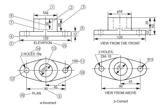
Figure 2a (Incorrect dimensioning) and Figure 2b (Correct dimensioning)
Reasons for the violations of some of the rules of dimensioning in Figures 2a and 2b
1. The dimension in 1 (i.e., 54) should follow the symbol (i.e., ϕ)—i.e., it should be ϕ54, not 54ϕ.
2/3. As much and far as possible, the features shouldn’t be used for dimensioning as extension lines.
4. The extension line should touch the feature instead of only being so close to it.
5. The extension line should project beyond the dimension line.
6. The dimension is not properly indicated as per the aligned system.
7. Hidden lines should intersect without any space.
8. The center line is wrongly represented, as a small dash should be used in place of a dot.
9. The horizontal dimension line should not be divided in that manner just to insert the value of the dimension.
10. The dimension should be placed above the dimension line, not below.
11. The radius symbol should be placed before the dimension, not after.
12. The center lines should cross each other at long dashes.
13. The dimension should be written beside a symbol, not beside an abbreviation.
14. Notes should be written in capital letters if they have a dimension.
15. Elevation is not the correct or appropriate term, as it is not specific.
16. The use of the term ‘‘plan’’ may not be appropriate because it depends on where one is taking a view or making a projection. More appropriate terms may be “view from above”, “view from front”, etc.
Conclusion
When dimensioning to create a properly illustrated object, structure, or feature, place the dimensions in such a way that they can be clearly viewed. If you need to, at a later time you can modify, change, or clean up the appearance of the dimensions to follow standard drawing practices.
Good dimensioning and dimension placement practices such as placing dimensions outside the outline of objects or structures and keeping them at a reasonable distance from one another will make it easier for your drawings or models to be understood or interpreted.


 Figure 10: Drawing board and drawing paper

 Figure 13: T-square
 Figure 14: Drawing compasses (for drawing circular and elliptical shapes)


